Directly Programming an ATmega328p from an Arduino Uno
So Arduino’s brains is a ATmega328p microcontroller. On the standard Arduino Uno, it comes as a chip that you can remove from the board, so if you fry it on accident, you can replace just the chip instead of the whole board. So is it possible to remove all the stuff Arduino gives you, take just the chip, and directly program the ATmega328p?
Well I came across a youtube playlist recently that gives a resounding yes, yes you can. Mitch Davis’ Bare-Metal MCU playlist walks you through taking all the helpful things Arduino gives you, and removing them one by one. This sort of content is exactly up my alley, and I realized I had an Uno kicking around, plus a sparkfun version of an Uno, a sparkfun redboard. Why not follow along? So, using Mitch Davis’ playlist as a basis, I decided to do the following:
- Take my existing Redboard, make it into an ISP (In-circuit Serial Programmer).
- Change the Fuse setting so the ATmega328p chip uses the internal clock instead of external
- Remove the ATmega328p chip from my arduino uno, put it on a breadboard
- validate the ATmega328p can run my blink program while sitting on the breadboard, getting no help from the Arduino PCB
- connect it to the ISP and flash a new program on it
- ???
- cackle at my brilliance
NOTE: that last step is non-optional when I’m playing with tech
This is a part of my series on programming atmega328p
For more posts on this, see below
- Directly Programming an ATmega328p from an Arduino Uno (You are Here)
- Programming an ATmega328p without the Arduino IDE
Making the redboard into an ISP
This was shockingly easy! The Arduino IDE comes with Arduino ISP code in the Examples section by default. So all I had to do was connect my redboard to my computer, then send the ISP code from the Arduino IDE to my redboard just like normal, and voila, I now have a ISP. Neat!
NOTE: going forward, I’ll refer to the Arduino Uno-compatible redboard as “the ISP” to reduce confusion on if I’m talking about the Arduino Uno I want to reprogram, or the arduino Uno-compatible sparkfun redboard I’m using as the ISP.
Connecting the ISP to the arduino Uno and Sending Code
Following Mitch’s tutorial, I have the following pin connections, from the ISP to Uno:
- 13 to 13
- 12 to 12
- 11 to 11
- 10 to reset
- 5v to 5v
- Gnd to Gnd
It’s all one-to-one except for pin 10 on the ISP to the reset pin on the Uno. This is because the ISP needs to muck with the reset pin in order to program the Uno. The Arduino ISP example code default uses pin 10 for that communication.
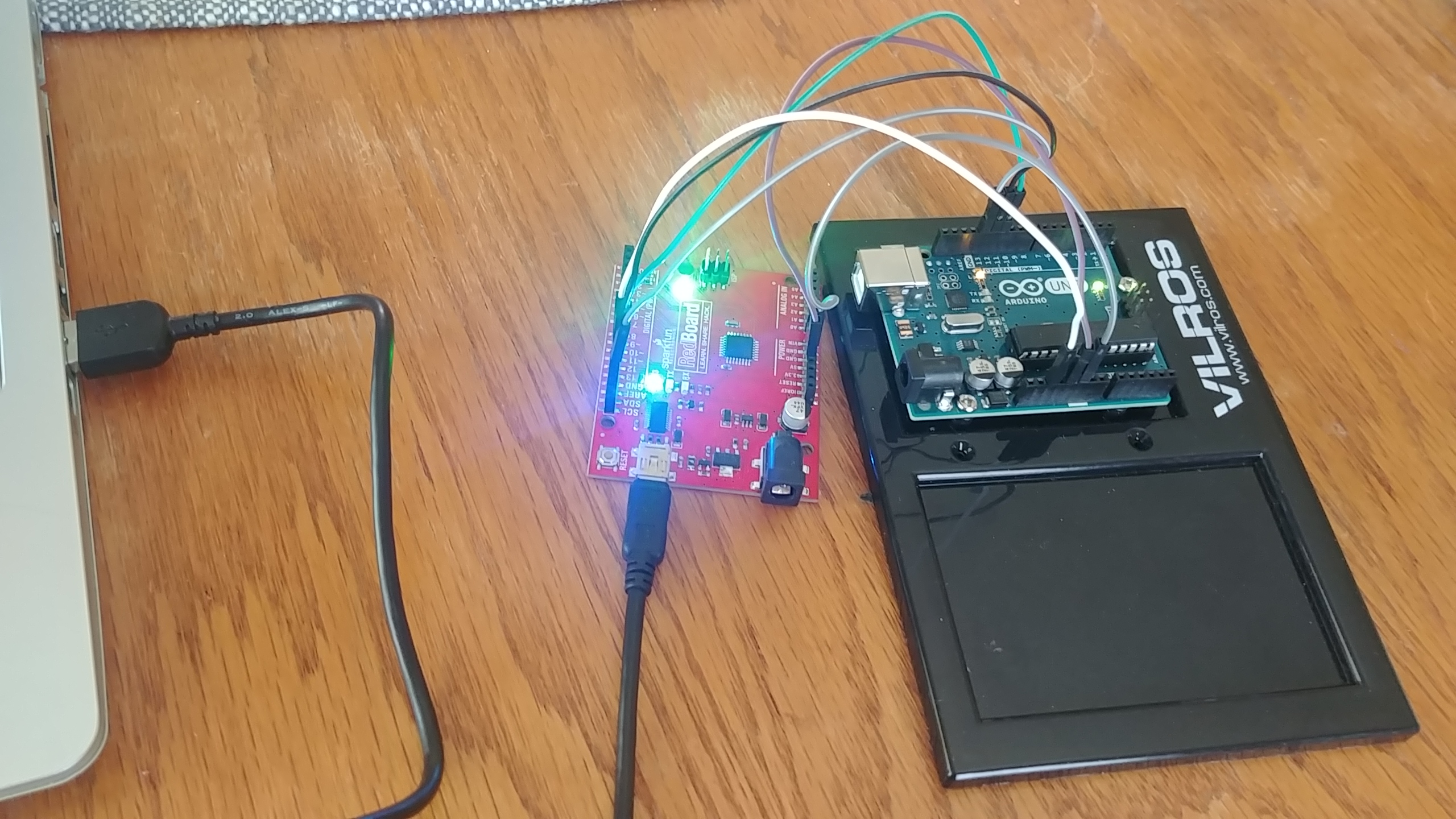 The ISP connected to the Arduino Uno
Reading Arduino’s documentation about the arduino ISP code and the comments in the ISP code, it says it uses 3 pins on the arduino you’re using as an ISP to give more info about the ISP. Connecting up pins 7, 8, and 9 on an Arduino Uno ISP (or redboard, in my case) to some LEDs and resistors let you see the heartbeat, error, and programming info. The comment in the code sums it up nicely:
// Put an LED (with resistor) on the following pins:
// 9: Heartbeat   - shows the programmer is running
// 8: Error       - Lights up if something goes wrong (use red if that makes sense)
// 7: Programming - In communication with the slave
Though the “slave” terminology seems to be a hold over from older code, since elsewhere it’s referred to as “target”. I hunted down the right github repo and did a pull request to update that line of code. So if that gets merged in, I’ll have technically contributed to the Arduino IDE example code base. Since it’s a comment it doesn’t change the runnable code one iota, but still.
Now I update the Arduino IDE to use “Arduino as ISP” as the Programmer (the setting is under the “tools” dropdown), and I can send the example blink.ino program to the Uno, using my brand new ISP! If I want to see more info about what the Arduino IDE is actually doing when it sends the code over, I can go to File -> Preferences, and set the “show verbose output during” checkboxes for both compilation and uploading. I then open the blink.ino sketch in the IDE, and upload it using Sketch->Upload using Programmer.
After sending the blink code to the uno, the on-board LED is flashing on my ISP and my uno. It took me a bit to figure that out. The blink program is makng LED_BUILTIN high and low to flash the built in LED on and off. Well LED_BUILTIN is just a constant that is referencing the pin on the arduino that is connected to the onboard LED. On the Uno, that’s pin 13. So after the ISP uses pin 13 to send data to the Uno, now the Uno is powering pin 13 on and off, and the wire is still connected to pin 13 on the ISP, so the ISP blinks too.
Looking in the logs the IDE prints out, I can find the command that arduino IDE used to flash the blink program onto the uno via the ISP.
/home/danielle/arduino-1.8.13-linux64/arduino-1.8.13/hardware/tools/avr/bin/avrdude -C/home/danielle/arduino-1.8.13-linux64/arduino-1.8.13/hardware/tools/avr/etc/avrdude.conf -v -patmega328p -cstk500v1 -P/dev/ttyUSB0 -b19200 -Uflash:w:/tmp/arduino_build_984737/Blink.ino.hex:i
This is an important thing to note. AVRDude is a utility to download/upload/manipulate the ROM and EEPROM contents of AVR microcontrollers using the in-system programming technique (ISP). (this is taken straight from their website) The ATmega328 is an AVR microcontroller, and I just made an ISP. Since it’s a command line tool, I can actually use the tool directly, without using the Arduino IDE. This is important for the fuse bytes that I’ll talk about shortly.
Now that I’ve figured out how to make an ISP, and proving it works, the next step I want to do is rip the ATmega328 off of the Uno so I can play with it directly. But first, I have to change a setting on the chip that Arduino sets at the factory.
Fuse Bits
There’s actually an in-depth blog post that talks about fuse bits in detail: https://embedderslife.wordpress.com/2012/08/20/fuse-bits-arent-that-scary/. But basically, they’re a series of bits that configure different settings on the microcontroller itself. Like a config file on a website that says what port it uses and routing info.
I care about this because of what Arduino does to the fuse bits in their factory. ATmega328 has a 8Hz oscillator on the chip that it uses as a clock, but it CAN run up to 16Hz (according to the datasheet). So Arduino adds a 16Hz oscillator on the Uno PCB and connects it to the ATMega328. This lets it run faster than when using the default 8Hz. But it also means, if the ATMega328 doesn’t have an oscillator hooked up, it just straight up can’t run, because it doesn’t know how to time anything!
So before removing the ATmega328 from the Uno, I have to update the fuse bits to go back to using the on-chip 8Hz clock. How? Why by using avrdude!
To read the low fuse byte, look at the arduino IDE verbose setting to see where the avrdude downloaded by arduino lives, and go there. Mine was in a /home/danielle/arduino-1.8.13-linux64/arduino-1.8.13/hardware/tools/avr folder. Then, I ran the following command
./bin/avrdude -C ./etc/avrdude.conf -v -p atmega328p -c stk500v1 -P /dev/ttyUSB0 -b 19200 -U lfuse:r:/tmp/lfusesetting:h
NOTE the baudrate setting to 19200 (using the
-b 19200flag), was required to get avrdude working. Otherwise I get a “Yikes! Invalid device signature.” error.
If you want to go in-depth on what all this means, you can read the avrdude docs here: https://www.nongnu.org/avrdude/user-manual/avrdude_4.html#Option-Descriptions. But basically I’m telling it:
- what chip I’m using (
atmega328p) - what ISP I’m using (though I lie and say
stk500v1instead of the arduino as ISP, because that’s what the IDE did) - where the ISP is on my computer (
/dev/ttyUSB0) - baud rate (
19200) - and what to do: for the low fuse byte (
lfuse), read (r) it, and write the value to/tmp/lfusesetting, as a hex (h) value
After I run that command, I use cat on /tmp/lfusesetting to get: 0xff, which is what Mitch Davis says the low fuse is default set to by Arduino.
To update it, I change just the clock select bits to 0010 so it uses the internal 8Hz oscillator. This would change the low fuse byte to 0xf2. So the command to update the low fuse is:
./bin/avrdude -C ./etc/avrdude.conf -v -p atmega328p -c stk500v1 -P /dev/ttyUSB0 -b 19200 -U lfuse:w:0xF2:m
Which outputs below:
avrdude: Version 6.3-20190619
        Copyright (c) 2000-2005 Brian Dean, http://www.bdmicro.com/
        Copyright (c) 2007-2014 Joerg Wunsch

        System wide configuration file is "./etc/avrdude.conf"
        User configuration file is "/home/danielle/.avrduderc"
        User configuration file does not exist or is not a regular file, skipping

        Using Port                    : /dev/ttyUSB0
        Using Programmer              : stk500v1
        Overriding Baud Rate          : 19200
        AVR Part                      : ATmega328P
        Chip Erase delay              : 9000 us
        PAGEL                         : PD7
        BS2                           : PC2
        RESET disposition             : dedicated
        RETRY pulse                   : SCK
        serial program mode           : yes
        parallel program mode         : yes
        Timeout                       : 200
        StabDelay                     : 100
        CmdexeDelay                   : 25
        SyncLoops                     : 32
        ByteDelay                     : 0
        PollIndex                     : 3
        PollValue                     : 0x53
        Memory Detail                 :

                                Block Poll               Page                       Polled
        Memory Type Mode Delay Size  Indx Paged  Size   Size #Pages MinW  MaxW   ReadBack
        ----------- ---- ----- ----- ---- ------ ------ ---- ------ ----- ----- ---------
        eeprom        65    20     4    0 no       1024    4      0  3600  3600 0xff 0xff
        flash         65     6   128    0 yes     32768  128    256  4500  4500 0xff 0xff
        lfuse          0     0     0    0 no          1    0      0  4500  4500 0x00 0x00
        hfuse          0     0     0    0 no          1    0      0  4500  4500 0x00 0x00
        efuse          0     0     0    0 no          1    0      0  4500  4500 0x00 0x00
        lock           0     0     0    0 no          1    0      0  4500  4500 0x00 0x00
        calibration    0     0     0    0 no          1    0      0     0     0 0x00 0x00
        signature      0     0     0    0 no          3    0      0     0     0 0x00 0x00

        Programmer Type : STK500
        Description     : Atmel STK500 Version 1.x firmware
        Hardware Version: 2
        Firmware Version: 1.18
        Topcard         : Unknown
        Vtarget         : 0.0 V
        Varef           : 0.0 V
        Oscillator      : Off
        SCK period      : 0.1 us

avrdude: AVR device initialized and ready to accept instructions

Reading | ################################################## | 100% 0.04s

avrdude: Device signature = 0x1e950f (probably m328p)
avrdude: safemode: lfuse reads as FF
avrdude: safemode: hfuse reads as DE
avrdude: safemode: efuse reads as FD
avrdude: reading input file "0xF2"
avrdude: writing lfuse (1 bytes):

Writing | ################################################## | 100% 0.05s

avrdude: 1 bytes of lfuse written
avrdude: verifying lfuse memory against 0xF2:
avrdude: load data lfuse data from input file 0xF2:
avrdude: input file 0xF2 contains 1 bytes
avrdude: reading on-chip lfuse data:

Reading | ################################################## | 100% 0.02s

avrdude: verifying ...
avrdude: 1 bytes of lfuse verified

avrdude: safemode: lfuse reads as F2
avrdude: safemode: hfuse reads as DE
avrdude: safemode: efuse reads as FD
avrdude: safemode: Fuses OK (E:FD, H:DE, L:F2)

avrdude done.  Thank you.
It’s cool it shows all fuse settings right now too, so I can compare with the data sheet to see what the fuse bits are currently set as.
NOTE: Figuring out what changes to the Fuse bits you should do is pretty confusing. And if you accidentally set the wrong bit, you could potentially brick the ATmega328p! There are fuse bit calculators out there that try to improve the process some though. The one Mitch uses is this one: http://eleccelerator.com/fusecalc/fusecalc.php?chip=atmega328p
Side track, the high fuse byte
Just for fun, let’s take a look at the current setting of the high fuse byte. Hfuse is 0xDE, which in binary is 1101 1110. Let’s go through it a nibble at a time (4 bits at a time).
The first four bits, 1101, are a series of individual settings. Going left to right, the first bit is if the reset pin works. This is needed for programming with the ISP. The documentation is kind of confusing on this one. Setting it to 0 means “on”, but the setting is “disable the reset pin”. So really, it’s 1 if the reset pin is enabled, 0 if not. The next bit turns off the debug wire setting (I don’t know what that means, but I’m not touching it). Next bit is enabling serial programming. We definitely want this enabled! And again, it’s kind of weird, because THIS bit’s setting is “enable serial programming”, and since 0 means “on”, we want to set this to 0. So it’s opposite of the reset pin bit, but the end result is enabling both the reset pin and serial programming. The last bit in this nibble sets if the watchdog timer is always on. It default sets to 1, which means the watchdog timer is not always on.
On to the next nibble! Continuing left to right, the first bit set to 1 which means it will not preserve EEPROM memory when the chip is erased.
The last three bits, 110, collectively set boot size. They set the boot flash size as 256 words, and the boot start address is 0x3F00. So this is setting the microcontroller so it knows that there’s a bootloader in flash memory in the range 0x3F00 - 0x3FFF, and on start up, it should start looking for instructions at 0x3F00. Cool!
But enough playing around, now that the low fuse byte is set, the ATmega328p should be able to run by itself, outside of the arduino Uno PCB board. Lets pry it off and see what happens!
Running Blink without the Uno
First, I have to pry off the ATmega328 without damaging the pins. It was in there tight, and one pin is a little wonky now, but they’re all still attached properly and it fits in the breadboard just fine. With the ATmega328 safely on the breadboard, I have to give it power and add an LED/resistor set up on pin 13, then it should work!
 The ATmega328p removed from the Uno and placed on a breadboard. I set it so row 1 on the breadboard is the same as physical pin 1, to help me wire it up correctly.
There’s only one problem, the ATmega328’s physical pin 13 doesn’t match with the digital pin 13 on the arduino Uno. But by using the Arduino pin mapping: https://www.arduino.cc/en/Hacking/PinMapping168 I can see that pin 13 on the Uno is actually physical pin 19 on the ATmega328. The mapping also shows the Vcc and ground on the ATmega328, so I have everything I need to power up the ATmega328 and see if it runs the blink program!
NOTE: When I say “physical pin X”, I’m talking about the pin on the ATmega328 that is labeled as X on the official pinout diagram. You can see it on that Arduino to ATmega328 pin mapping image above, or in the documenation here: http://ww1.microchip.com/downloads/en/DeviceDoc/ATmega48A-PA-88A-PA-168A-PA-328-P-DS-DS40002061A.pdf, just do a
ctrl+ffor “pinout” to find the right form factor.
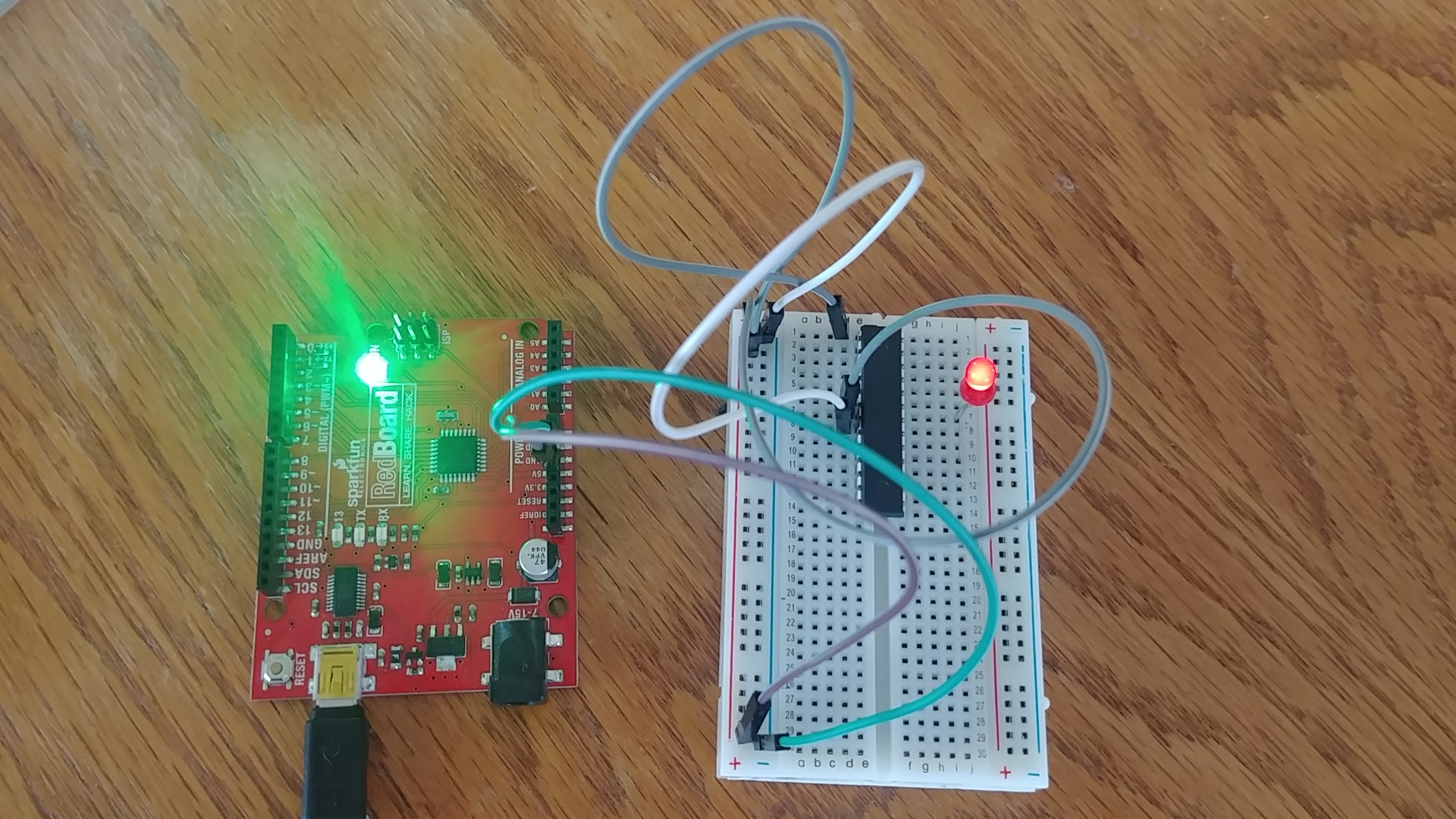 The ATmega328p is getting power from the ISP, but nothing else. If I set the fuse bits correctly, it’s using it’s internal oscillator as a clock and running my blink code.
NOTE: the LED in this picture doesn’t have a resistor attached to it. That’s because this particular LED actually has a built-in resistor, since it’s from an intro-to-microcontrollers kit, and they didn’t want accidental frying of LEDs, apparently.
Success! The LED blinks! Notice I also have a wire coming from the physical pin 1 to the positive voltage. This is the reset pin on the ATmega328, and I add that because if the reset pin gets pulled low at some point, it will reset the ATmega328. I don’t want that, so for now, I just connect it with the 5.5v power source and call it good.
Flashing New Programs on the ATmega328
Using the Uno to ATmega328 mapping that Arduino gives me, I can add wires between the ISP and the ATmega328 so I can put new programs onto it. This way I don’t have to put it back into the Uno PCB every time! The connections, from ISP to ATmega328 are:
- 13 to physical pin 19
- 12 to physical pin 18
- 11 to physical pin 17
- 10 to physical pin 1 (reset)
- 5v to physical pin 7 (already done, to power the ATmega328)
- Gnd to physical pin 8 (already done, to power the ATmega328)
NOTE: since the ISP pin 13 is connected to the physical pin 19 (which is where the LED is), once again the ISP’s onboard LED will light up in time with the ATmega328.
 With that set up done, I should be able to flash a new program on the ATmega328 with the Arduino IDE.
And as a fun side bonus, since the LED is physical pin 19, which doubles as the clock pin for the ISP, we’ll see the LED flash while the data is getting put onto the ATmega328. LED flashing = flashing the program. Fun!
I updated the blink.ino file in a very complicated way, to make sure I could tell when I had successfully flashed a new copy of blink.ino onto the ATmega328, then sent it using the Arduino IDE “upload using programmer” option. A few seconds of flashing later, I had my results. Success again!
Here’s my “complicated” updated code. I made it blink twice with different waits, so it’s clear this is the new version. The old version I had running was the standard blink program.
void loop() {
    digitalWrite(LED_BUILTIN, HIGH);   // turn the LED on (HIGH is the voltage level)
    delay(250);                       // wait for a second
    digitalWrite(LED_BUILTIN, LOW);    // turn the LED off by making the voltage LOW
    delay(500);                       // wait for a second
    digitalWrite(LED_BUILTIN, HIGH);   // turn the LED on (HIGH is the voltage level)
    delay(500);                       // wait for a second
    digitalWrite(LED_BUILTIN, LOW);    // turn the LED off by making the voltage LOW
    delay(500);                       // wait for a second
}
Conclusion
I’ve managed to yank the poor ATmega328p from its safe Uno home and showed it a wider world. Next up, I’ll start removing my dependence on the Arduino IDE. Eventually, I’m hoping I’ll understand the whole toolchain needed for programming the ATmega328p, and by extension, AVR microcontrollers in general. Maybe as I learn more about lower level embedded programming, I can think about building custom embedded systems!
Resources
Mitch Davis’ playlist on breaking down the arduino Uno into bare metal: https://www.youtube.com/playlist?list=PLNyfXcjhOAwOF-7S-ZoW2wuQ6Y-4hfjMR
The ATmega328 datasheet. This is specifically for the ATmega328P, but doesn’t have the pinout for the form factor the arduino Uno uses. Look at the generic ATmega328 datasheet below for that http://ww1.microchip.com/downloads/en/DeviceDoc/Atmel-7810-Automotive-Microcontrollers-ATmega328P_Datasheet.pdf
Generic ATmega328 and a couple of other microcontrollers datasheet. Includes the pinout for the ATmega328 used in the Uno http://ww1.microchip.com/downloads/en/DeviceDoc/ATmega48A-PA-88A-PA-168A-PA-328-P-DS-DS40002061A.pdf
AVR Fuse Calculator - http://eleccelerator.com/fusecalc/fusecalc.php?chip=atmega328p
Pin mapping from arduino - https://www.arduino.cc/en/Hacking/PinMapping168
AVRDude command line option doc: https://www.nongnu.org/avrdude/user-manual/avrdude_4.html#Option-Descriptions
Arduino’s documentation for the Arduino ISP https://www.arduino.cc/en/pmwiki.php?n=Tutorial/ArduinoISP
Sparkfun’s hookup guide https://learn.sparkfun.com/tutorials/installing-an-arduino-bootloader#hardware-hookup