Using Interrupts on the Adafruit Feather Huzzah with ESP8266
It doesn’t take long learning embedded systems before you come across interrupts. Learning how to make your embedded system quickly react to changes in the real world (button presses, motion sensing, whatever) is often a default requirement for any fun projects. Since I’ve been programming on the Adafruit Feather Huzzah with ESP8266 (a mouthful, I have to say), I decided to use that for some hands-on learning.
The Plan
Do some basic interrupts and learn more about how to use them with the ESP8266. A basic interrupt example that I’ve seen around a lot is turning on an LED for a certain amount of time when a button is pressed. So let’s do that!
NOTE I’m assuming in this post you already have the setup to run the Arduino IDE and write programs for the ESP8266.
Hardware
Hardware needed:
- Adafruit Feather Huzzah w/ ESP8266, with soldered on headers
- Breadboard
- Jumper wires
- LED
- 300 Ohm Resistor
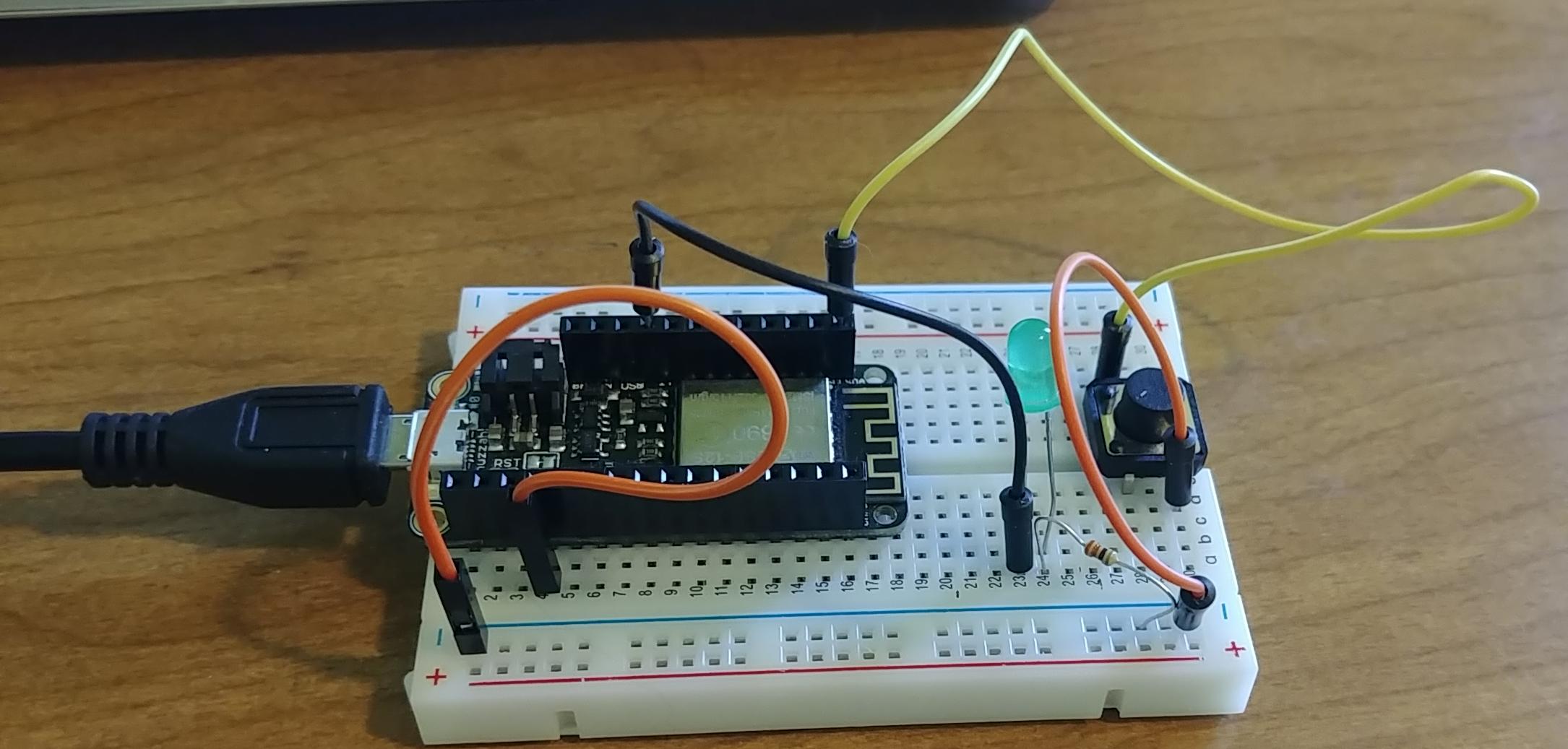
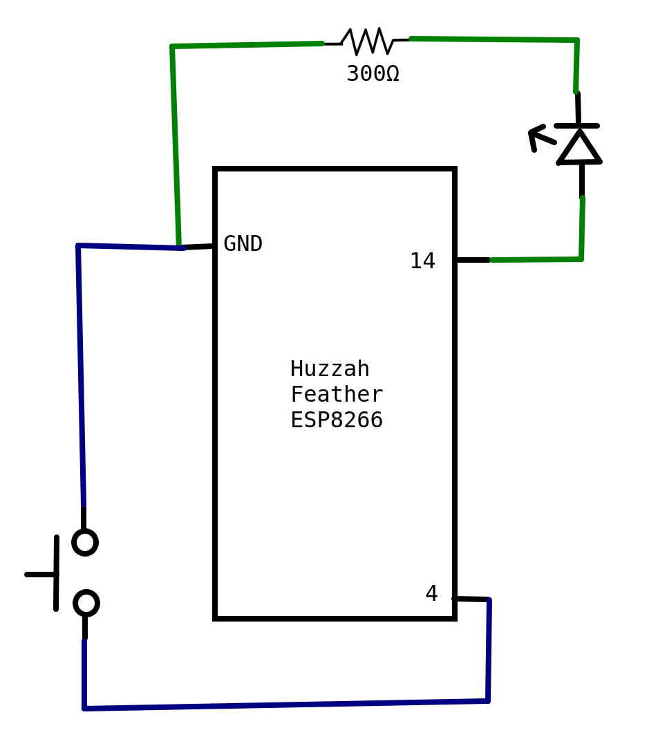
To wire up the circuit I’ll be using, attach the LED and resistor in series, and connect to pin 14 and ground on the feather. Then attach the momentary switch to pin 4 and ground. Below is a simple drawing showing the circuit. The wire color in the diagram is just for visual clarity.
Without Interrupts
First, lets get the basic functionality working without interrupts. Note that I set the momentary switch as a pull up. This means when the switch is not pressed, I’ll read the pin as HIGH, and when it’s pressed, it’ll go to LOW. If I didn’t set it, the pin would not be guaranteed either HIGH or LOW, and reading the state of pin 4 wouldn’t tell me if the button was pushed or not!
I also used the millis() function instead of delay(). This is because delay doesn’t let me do anything else while I’m waiting for the LED to finish being on. If I want to use this code to do other things while the LED is on, I have to instead track the time since it was turned on, so I can do other things in the loop() too.
#define GPIO_INTERRUPT_PIN 4
#define LED_PIN 14
#define WAIT_TIME 500

unsigned long lastTrigger = millis();
bool buttonPressed = false;

void setup() {
  //Start serial
  Serial.begin(115200);
  Serial.println("Starting sketch");

  //Set the LED pin to output
  pinMode(LED_PIN, OUTPUT);
  //set the eventual interrupt pin as an input that is pulled up
  pinMode(GPIO_INTERRUPT_PIN, INPUT_PULLUP);

}

void loop() {

  if (!buttonPressed && digitalRead(GPIO_INTERRUPT_PIN) == LOW){
    Serial.println("Button pressed");
    digitalWrite(LED_PIN, HIGH);
    buttonPressed = true;
    lastTrigger = millis();
  }

  if (buttonPressed && lastTrigger + WAIT_TIME < millis()){
    digitalWrite(LED_PIN, LOW);
    buttonPressed = false;
  }

  //Other functionality goes here...

}
Of course most code isn’t only checking a button. Let’s add a delay in there to simulate doing other work.
#define GPIO_INTERRUPT_PIN 4
#define LED_PIN 14
#define WAIT_TIME 500

unsigned long lastTrigger = millis();
bool buttonPressed = false;

void setup() {
  //Start serial
  Serial.begin(115200);
  Serial.println("Starting sketch");

  //Set the LED pin to output
  pinMode(LED_PIN, OUTPUT);
  //set the eventual interrupt pin as an input that is pulled up
  pinMode(GPIO_INTERRUPT_PIN, INPUT_PULLUP);

}

void loop() {

  if (!buttonPressed && digitalRead(GPIO_INTERRUPT_PIN) == LOW){
    Serial.println("Button pressed");
    digitalWrite(LED_PIN, HIGH);
    buttonPressed = true;
    lastTrigger = millis();
  }

  if (buttonPressed && lastTrigger + WAIT_TIME < millis()){
    digitalWrite(LED_PIN, LOW);
    buttonPressed = false;
  }

  //Other functionality goes here...
  delay(500);

}
If you upload this code to the feather, you can see the button press is erratic. First, if you mess with the delay time, you can see that once the number of milliseconds you delay is longer than WAIT_TIME, the LED will stay on longer. This is because turning off the LED is in the loop() function with everything else, so while it’s in the delay, the code can’t turn the LED off!
Second, it doesn’t always register that the button was pressed. When it’s in the delay function (aka doing other stuff), it’s not checking if the button has switched to LOW (aka been pressed). Completely missing a button press is not acceptable for pretty much any project! Let’s fix that.
Basics of Interrupts
Interrupts are a way to interrupt the standard flow of your program. In my particular case, I want to interrupt whatever I’m doing in my loop() function and turn on the LED when I press the button.
The steps of a generic interrupt happening are:
- The ESP8266 is running code (both overhead and code in my
loopfunction) - Something happens that I told the ESP8266 in my
setupfunction needs to trigger an interrupt - The ESP8266 stops whatever is currently happening and saves the context so it can get back to it later
- The ESP8266 looks up what it’s supposed to do when the trigger happens (aka looks for my interrupt handler code)
- It runs my handler code
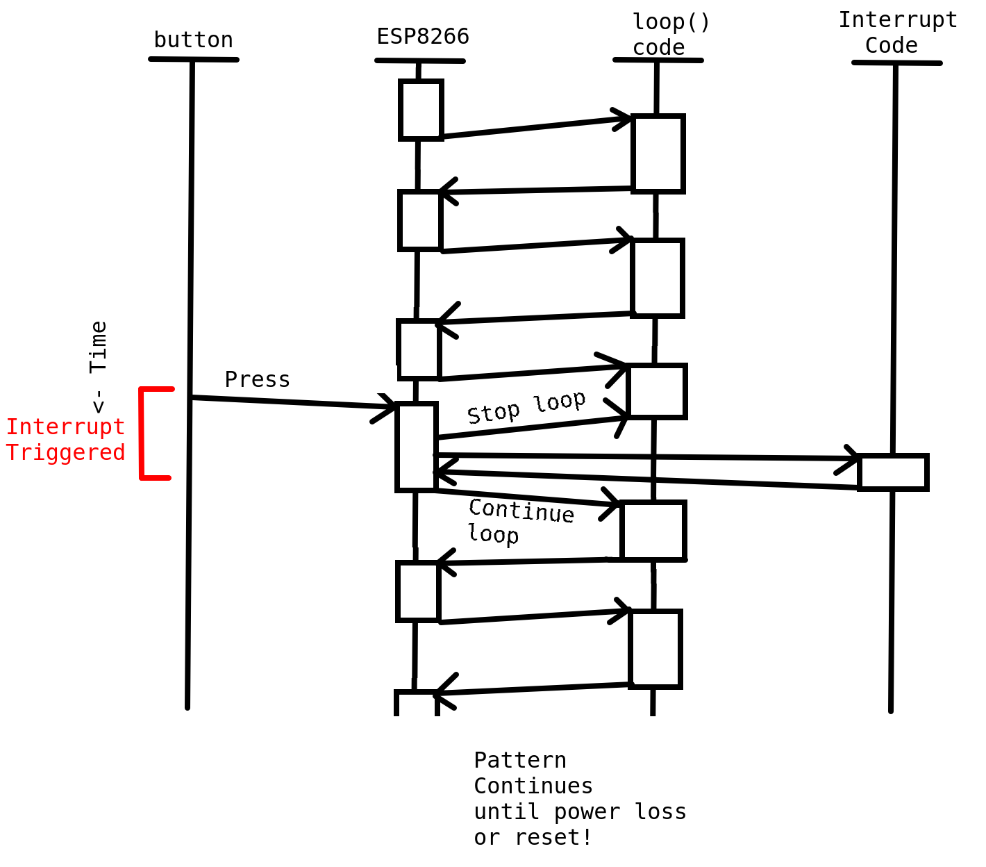
- Once that’s done, it pulls the saved context back into its proper place, and starts up whatever it was doing before the interrupt happened.
I also made a timing diagram of the button press interrupt happening, to give a more visual represenation.
So, to make this interrupt I want a reality, I have some basic setup to do:
- Define what I want to happen when the interrupt triggers (i.e. turn on the LED and set some variables to control how long the LED is on). This will be my interrupt handler function, also known as an interrupt service routine or ISR.
- Set how I want to trigger the interrupt. In my case, I want to trigger on a GPIO pin.
- Since I’m triggering off of a GPIO pin, I need to set what state I want to trigger on. Some example options would be rising (when it goes from
LOWtoHIGH), falling (when it goes fromHIGHtoLOW), or whenever there’s a change.
Arduino Specifics
Arduino has a builtin function attachInterrupt that lets me set what pin and when to trigger the interrupt. They have a write up here: https://www.arduino.cc/reference/en/language/functions/external-interrupts/attachinterrupt/. It’s pretty straightforward. Call attachInterrupt with the pin to watch, the function to call when it triggers, and when to trigger it.
Arduino has default constants you can use for when to trigger the interrupts. They are:
LOW to trigger the interrupt whenever the pin is low,
CHANGE to trigger the interrupt whenever the pin changes value
RISING to trigger when the pin goes from low to high,
FALLING for when the pin goes from high to low.
Since I want to trigger off my button attached to pin 4, and I want to trigger it when the pin goes from LOW to HIGH (aka when a person lifts their finger off the button), I can setup the interrupt with the below code:
attachInterrupt(digitalPinToInterrupt(GPIO_INTERRUPT_PIN), detectsButton, RISING);That detectsButton argument is the name of the interrupt handler function. Which has to be defined a little different from what the arduino documentation says because I’m using the ESP8266.
ESP8266 Specifics
The ESP8266 has a slightly different setup than the standard chips used in Arduinos, which results in an extra step. When declaring the interrupt function, you have to prepend ICACHE_RAM_ATTR to the function definition. This tells the linker to put this function in RAM instead of flash, where the rest of the program goes. The exact reasons why seem a bit murky. Different posts and forum questions online give no reason beyond “you gotta put this here”, or give different reasons why. But the basics as I understand it is that the interrupt handler (aka the code that runs during the interrupt) needs to be stored in RAM on the ESP8266, not flash, where it would normally be stored without that ICACHE_RAM_ATTR. This is because the interrupt code can run at any time, and if the chip is in the middle of writing or reading to flash, trying to also run the interrupt handler code in flash at the same time will cause the chip to crash. Crashing is bad, so the ESP8266 Arduino code has a built-in check to make sure all interrupt handlers are in the RAM. If it’s not, the code will pre-emptively crash with an error that says “ISR not in IRAM!”.
So the detectsButton function is defined as follows:
ICACHE_RAM_ATTR void detectsButton() {
  //NOTE because in ISR, millis() call will return the same value every time

  //only trigger if I didn't just trigger DEBOUNCE_TIME ago
  //lastTrigger > millis() means millis has overflowed
  if (lastTrigger > millis() || lastTrigger+DEBOUNCE_TIME < millis())
  {
    lastTrigger = millis();
    buttonPressed = true;
  }
  else{
    bounce++;
  }

}
There’s a couple things to note here. One, my comment that starts with “NOTE” that talks about the millis function. The millis() function returns the number of milliseconds it’s been since the chip turned on. It actually uses interrupts in order to update! That interrupt is setup by the Arduino code, which is why I don’t have to setup that interrupt in my code. However, Arduino disables interrupts when you’re running an interrupt handler. Presumably so you don’t get interrupts triggering while you’re handling an interrupt and just get lost in nested interrupts forever. But this means the interrupt to update the return value for millis() wont run, and so it’ll return the same value the entire time you’re in an interrupt handler.
Second, there’s a check lastTrigger+DEBOUNCE_TIME < millis() that happens before it actually updates that the button was pressed. The ESP8266 says that the button has changed from LOW to HIGH, which is why it’s running this code, so why am I adding extra checks? It’s because of debouncing. The analog world can be messy (citation needed), so when the button is first pressed, or first released, the reading on pin 4 can bounce between LOW and HIGH a bit before it settles down on one or the other. During that time, the interrupt can get triggered several times. But I only want it to actually trigger once! So I add a check in there. If the last time the button was triggered was really recent (aka within DEBOUNCE_TIME milliseconds), then I assume this trigger was the button bouncing a bit, and ignore it. Because I was curious, though, I don’t completely ignore it. Instead I set the bounce++ to add to my total bounce amount. In my loop code I check that variable and output to serial that I bounced, just so I could see how often it happens.
Lastly, there’s a check for lastTrigger > millis() which at first glance doesn’t make sense. ThelastTrigger variable is set to millis() from the last time it was triggered, and the number of milliseconds since the chip was turned on will only go up (we’re not time-traveling!). So how can this check ever return true? The answer is overflow! The number of milliseconds since turn on is stored in an unsigned long variable. Since it’s unsigned, the variable is always positive, and since it’s a long, its size is 32 bits. This means the max number of milliseconds it can store is 232 - 1, aka 4294967295 milliseconds. Convert that to days, and you get 49.7103009259 days, aka around 50 days (which the Arduino documentation on millis() says). Once it gets to that number, and you add one more millisecond, the number is 33 bits long! So the code just gets rid of the topmost number, and suddenly you’re getting 0 milliseconds from millis(). Now, I’m unlikely to run this test code for 50 days, so I don’t really need it, but I like to be complete when I can.
Final Code
Now that I have all that preamble out of the way, I can put together final example code using interrupts on the ESP8266.
#define GPIO_INTERRUPT_PIN 4
#define LED_PIN 14
#define WAIT_TIME 250
#define DEBOUNCE_TIME 10


volatile bool buttonPressed = false;
volatile unsigned long lastTrigger = millis();
volatile int bounce = 0;
int prevBounceCount = 0;

ICACHE_RAM_ATTR void detectsButton() {
  //NOTE because in ISR, millis() call will return the same value every time

  //only trigger if I didn't just trigger DEBOUNCE_TIME ago
  //lastTrigger > millis() means millis has overflowed
  if (lastTrigger > millis() || lastTrigger+DEBOUNCE_TIME < millis())
  {
    lastTrigger = millis();
    buttonPressed = true;
  }
  else{
    bounce++;
  }

}

void setup() {
  Serial.begin(115200);
  Serial.println("Starting sketch");
  pinMode(LED_PIN, OUTPUT);
  pinMode(GPIO_INTERRUPT_PIN, INPUT_PULLUP);

  attachInterrupt(digitalPinToInterrupt(GPIO_INTERRUPT_PIN), detectsButton, RISING);

}

void loop() {

  //lastTrigger > millis() means millis has overflowed
  if (buttonPressed && (lastTrigger > millis() || lastTrigger+WAIT_TIME <= millis())){
     Serial.println("button was pressed, time to turn off LED");
     digitalWrite(LED_PIN, LOW);
     buttonPressed = false;
  }
  else if (buttonPressed){
    digitalWrite(LED_PIN, HIGH);
  }
  if (bounce != prevBounceCount){
    Serial.println("Debounced");
    prevBounceCount = bounce;
  }

  //Other functionality goes here...
  delay(250);

}
Notice how several variables are declared to be volatile. This is important! Setting variables to volatile is me telling the compiler that the variables may change at any time outside the standard code flow. I set them to volatile in the code so the compiler knows not to optimize them out, or to used a cached value. In this case, I’m setting several variables to volatile because I set them in the interrupt handler. Which means every time I access them in the loop() function, it’s possible that the interrupt had happened just before it, and changed those variables! This is important info for the compiler to know, and makes it so the compiled version of my code is actually what I want it to be. Embedded FM has a short article about volatile if you want to learn more: https://embedded.fm/blog/2017/2/23/explaining-the-c-keyword-volatile
Now when a button is pressed (and released), the LED turns on immediately! Take some time to repeatedly press the button to turn on the LED and marvel at your new-found knowledge.
Note, however, that this works completely as intended only as long as the other functionality in the loop() doesn’t take longer than WAIT_TIME to complete. If the other functionality takes longer, than the if statement checking how long it’s been since last trigger won’t run in time, and the LED will stay on longer than WAIT_TIME. This is because turning the LED off is in the loop function, and so still restricted by all the other work done there. If you want an exact timing for how long the LED is on, then you’d have to add an interrupt that triggers on time, and that is outside the scope of this post. The ESP8266 does have timer interrupts, but that requires an extra library and more testing/playing around, so I’ll leave that as a potential future post.
In the meantime, enjoy your new knowledge, and go forth and interrupt things!
References
- Arduino’s way of adding interrupts: https://www.arduino.cc/reference/en/language/functions/external-interrupts/attachinterrupt/
- In-depth article about Arduino interrupts (focused on AVR but applicable to ESP8266): http://gammon.com.au/interrupts
- ESP8266 and Arduino specific interrupts: https://randomnerdtutorials.com/interrupts-timers-esp8266-arduino-ide-nodemcu/
- Arduino Documentation for
millis(): https://www.arduino.cc/reference/en/language/functions/time/millis/ - ESP8266 Arduino interrupt documentation: https://arduino-esp8266.readthedocs.io/en/latest/reference.html#interrupts
- The book Making Embedded Systems by Elicia White has a section talking about interrupts that I referenced while writing this post: https://www.oreilly.com/library/view/making-embedded-systems/9781449308889/