How to use Quadrature Rotary Encoders
As part of a project I’m working on, I wanted to have a nice rotating switch that let me flip between different options. Googling around, I discovered that apparently meant I needed a rotary encoder. I bought one from adafruit, only to realize I had no idea how to use it. And oddly enough, Adafruit didn’t have a pre-existing codebase I could pull from. It was time to read some datasheets, do some experiments, and figure out how to use it.

The Hardware
I bought the rotary encoder + extras from adafruit. I had originally thought to grab one from digikey or elsewhere (if only to get used to buying from other places), but the sheer amount of variables I had to know about frazzled me. How many detents are enough? What are pulses per revolution? Adafruit just gives you one option. It’s a rotary encoder, what more do you need to know! Adafruit provides a one and done, and sometimes, that’s what you want to do. Once I got it, I put the knob on it and gave it a twirl. A very satisfying clicky twisting motion, exactly what I wanted! Now to do some reading.
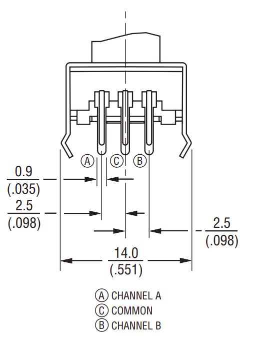
Adafruit provides the datasheet, so I can see what’s what.
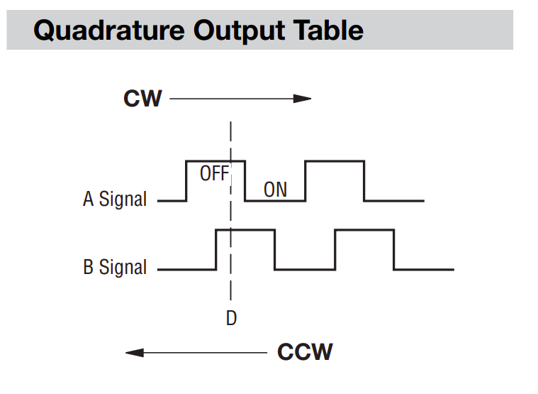
The 3 connector prongs on one side are the A, B and common (aka ground) channels. If I connect up to them and monitor A and B as I turn the knob, I should see the pattern specified in the Quadrature table.
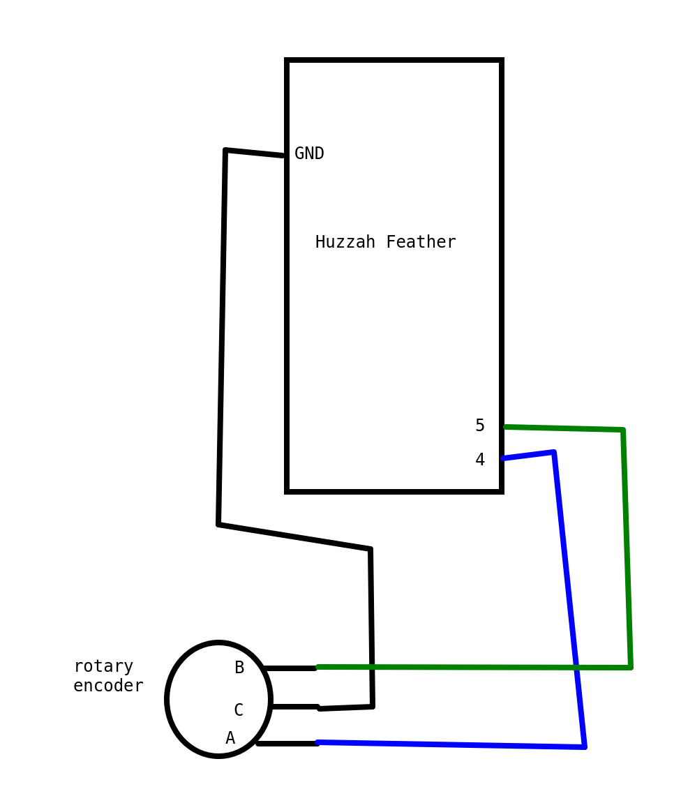
Since I started only kind of understanding this information (and frankly was just confused by that signal schematic), I decided to do some testing. Since I wanted to use the encoder with the adafruit feather huzzah with ESP8266, I wired up the simplest circuit I could, connecting channel A on the encoder to pin 4, channel B to pin 5, and the common to ground. Diagram below:
The First Test
The simplest test is to see what happens to things on channel A and B when I turn the knob. If you look back at the Quadrature table, you can see when both signals are HIGH, it means it’s off. And the way I wired it requires the pins to be pullups. So for this rotary encoder, when nothing is happening, they’re both set to HIGH, and when I turn the knob, they go down to low, one right after the other.
#define PIN_ENCODER_A      4
#define PIN_ENCODER_B      5

void setup() {
  Serial.begin(115200);
  pinMode(PIN_ENCODER_A, INPUT_PULLUP);
  pinMode(PIN_ENCODER_B, INPUT_PULLUP);

}

void loop() {
  int valA = digitalRead(PIN_ENCODER_A);
  int valB = digitalRead(PIN_ENCODER_B);

  //since these are default HIGH (aka have a pullup resistor)
  //either being set to LOW means something is happening on the encoder
  if (valA == LOW || valB == LOW){
    Serial.print(valA);
    Serial.print(" ");
    Serial.println(valB);
  }

}
With this code running on my feather, I can turn the know clockwise and counter clockwise, and see what I get.
Turned clockwise, for each “click” of the knob, I get this:
| pin A | pin B |
|---|---|
| 1 | 1 |
| 0 | 1 |
| 0 | 0 |
| 1 | 0 |
| 1 | 1 |
If I want, I can just put those two values next to each other and get a binary number. So it goes from 11, to 01, to 00, to 10, to 11. With the decimal equivalent being: 3, 1, 0, 2, 3
So if I track the previous state and the current state, I can tell it’s going clockwise if any of these are true:
previous state->current state
3->1
1->0
0->2
2->3
From this I can see I’ll have to at least track current and previous state, because it matters what state it’s coming from. Just knowing current state is “0” doesn’t mean anything about direction.
Let’s see if that pattern is different when it’s turned counter-clockwise. The values end up being:
| pin A | pin B |
|---|---|
| 1 | 1 |
| 1 | 0 |
| 0 | 0 |
| 0 | 1 |
| 1 | 1 |
Which is a different pattern! That’s good, otherwise I’d have to come up with a completely different way of figuring this out. In decimal, it would be: 3, 2, 0, 1, 3
So it’s going counterclockwise if:
3->2
2->0
0->1
1->3
Second Test - Lookup tables
Since I’ll have to do this in code eventually anyway, let’s do 1 to mean clockwise and -1 to mean counter clockwise. I can then list out all possible combinations of a previous and current state, and determine which way I’m going, or if I’m missing anything.
| previous state | current state | direction |
|---|---|---|
| 0 | 0 | UNDEFINED |
| 0 | 1 | -1 |
| 0 | 2 | 1 |
| 0 | 3 | UNDEFINED |
| 1 | 0 | 1 |
| 1 | 1 | UNDEFINED |
| 1 | 2 | UNDEFINED |
| 1 | 3 | -1 |
| 2 | 0 | -1 |
| 2 | 1 | UNDEFINED |
| 2 | 2 | UNDEFINED |
| 2 | 3 | 1 |
| 3 | 0 | UNDEFINED |
| 3 | 1 | 1 |
| 3 | 2 | -1 |
| 3 | 3 | UNDEFINED |
Based on this, I can see there’s a lot of options that don’t mean the encoder went clockwise OR counter clockwise. Looking at those undefined values, there’s two separate groups. If the previous and current values from the encoder are the same, that just means I read the values so fast, it didn’t have time to change (or in the case of 3, the encoder isn’t moving at all). So those just mean it didn’t move. For the other group of undefined values, they’re harder to categorize. Going from 0 to 3 means EITHER I moved clockwise so fast I went from 0 to 2 to 3 before my code had a chance to read the encoder values, OR I moved it counter clockwise so fast I went from 0 to 1 to 3. So that tells me the encoder rotated, but I don’t know which way! I’m not sure how to solve that, so I’m just going to treat that as a different “SKIPPED VALUE” category.
I can reorganize the data to make it a bit more readable (at least to me), by putting the previous value as the first column, and the current value as the first row, like this:
| 0 | 1 | 2 | 3 | |
| 0 | DIDN’T MOVE | -1 | 1 | SKIPPED A VALUE |
| 1 | 1 | DIDN’T MOVE | SKIPPED A VALUE | -1 |
| 2 | -1 | SKIPPED A VALUE | DIDN’T MOVE | 1 |
| 3 | SKIPPED A VALUE | 1 | -1 | DIDN’T MOVE |
Well hey, that looks an awful lot like a lookup table, a 4x4 array with the indices corresponding to the values. Let’s do that! For the “DIDN’T MOVE” category, I can just set it to 0, and for when I skip values, I’ll do 2, a clearly wrong value. With that, I get the below table:
{0, -1, 1, 2}
{1, 0, 2, -1}
{-1, 2, 0, 1}
{2, 1, -1, 0}
With this planning, I can now try some code out and see if it works.
#define PIN_ENCODER_A      4
#define PIN_ENCODER_B      5

int prevVal = 0;
int newVal;

int lookupTable[4][4] = { {0, -1, 1, 2},
                          {1, 0, 2, -1},
                          {-1, 2, 0, 1},
                          {2, 1, -1, 0} };

void setup() {
  Serial.begin(115200);
  pinMode(PIN_ENCODER_A, INPUT_PULLUP);
  pinMode(PIN_ENCODER_B, INPUT_PULLUP);

  int valA = digitalRead(PIN_ENCODER_A);
  int valB = digitalRead(PIN_ENCODER_B);
  prevVal = (valA << 1) + valB;

}

void loop() {
  int valA = digitalRead(PIN_ENCODER_A);
  int valB = digitalRead(PIN_ENCODER_B);
  newVal = (valA << 1) + valB;

  int info = lookupTable[prevVal][newVal];


  if (info == 1){
    Serial.print("clockwise ");
    Serial.print(prevVal);
    Serial.print("->");
    Serial.println(newVal);
  }
  else if (info == -1){
    Serial.print("counter clockwise ");
    Serial.print(prevVal);
    Serial.print("->");
    Serial.println(newVal);
  }
  else if (info == 2){
    Serial.println("skipped a value");
  }

  prevVal = newVal;
}
Final Code - Tracking State
This correctly understands clockwise and counterclockwise movement. HOWEVER, there’s two issues. One, it’s triggering roughly 4 times each detent, and Two sometimes the code manages to get a bounce or something else wonky, and it reads, say, 3 clockwise and one counterclockwise movement while I’m moving it clockwise. So I want to track all the states it passes through, and then figure out which way its going, ignoring those occasional misreads.
NOTE “detent” is a fancy word for that “click” feeling you get with rotary encoders. Each “click” position is a detent.
#define PIN_ENCODER_A      4
#define PIN_ENCODER_B      5

int prevVal = 0;
int newVal;
unsigned int clockState = 0;
unsigned int counterClockState = 0;

//lookup table, first index is previous value
//second index is current value
//says if it's part of the sequence when moving
//clockwise (1) or counterclockwise (-1)
//didn't move (0) or skipped a value (2)
int lookupTable[4][4] = { {0, -1, 1, 2},
                          {1, 0, 2, -1},
                          {-1, 2, 0, 1},
                          {2, 1, -1, 0} };

void setup() {
  Serial.begin(115200);
  pinMode(PIN_ENCODER_A, INPUT_PULLUP);
  pinMode(PIN_ENCODER_B, INPUT_PULLUP);

  int valA = digitalRead(PIN_ENCODER_A);
  int valB = digitalRead(PIN_ENCODER_B);
  prevVal = (valA << 1) + valB;

}

void loop() {
  int valA = digitalRead(PIN_ENCODER_A);
  int valB = digitalRead(PIN_ENCODER_B);
  newVal = (valA << 1) + valB;

  int info = lookupTable[prevVal][newVal];


  if (info == 1){
    clockState |= (1 << newVal); //set the bit to 1
  }
  else if (info == -1){
    counterClockState |= (1 << newVal);
  }
  else if (info == 2){
    Serial.println("skipped a value");
  }

  if (prevVal != newVal && newVal == 3){
    //changed to the non moving state, lets figure out what direction we went!

    //for each clockwise and counterclockwise, the encoder state goes through 4 distinct states
    //make sure it's gone through at least 3 of those (and assume if one is missing it's because I didn't read fast enough)
    if (clockState == 0b1011 || clockState == 0b1101 || clockState == 0b1110 || clockState == 0b1111){
      Serial.println("Result was clockwise");
    }
    if (counterClockState == 0b1011 || counterClockState == 0b1101 || counterClockState == 0b1110 || counterClockState == 0b1111){
      Serial.println("Result was COUNTER clockwise");
    }

    clockState = 0;
    counterClockState = 0;

  }

  prevVal = newVal;
}
This seems to work! I get a single “result was blah” for every turn, and it seems to be the correct rotation, too! The remaining issue depends on the other code I use this with. This code assumes I’ll be able to read at least 3 out of the 4 states the rotary encoder goes through every time it turns left or right. If I’m checking the encoder in a main loop, and my other code goes really slow, I may only get one or two states. An alternative to this would be setting up an interrupt, so it jumps to reading the encoder every time it changes state. However, interrupts are outside the scope of this blog post, so I’ll leave that as an exercise for the reader.
Conclusion
Hopefully this gives more info on what to expect when using a rotary encoder in your future projects. It’s a lot more complicated than a potentiometer, but that lovely clicky feeling can be perfect for switching between a bunch of options. And now you have the knowledge to use them. So go forth and get clicky!
Resources
- Datasheet for the rotary encoder https://cdn-shop.adafruit.com/datasheets/pec11.pdf
- Sparkfun document talking about reading rotary encodershttps://cdn.sparkfun.com/datasheets/Robotics/How%20to%20use%20a%20quadrature%20encoder.pdf
- Learning about the Arduino IDE serial plotter https://diyrobocars.com/2020/05/04/arduino-serial-plotter-the-missing-manual/
- Adafruit’s example using a rotary encoderhttps://learn.adafruit.com/pro-trinket-rotary-encoder/example-rotary-encoder-volume-control
- Document about rotary encoders https://web.archive.org/web/20120208215116/http://www.circuitsathome.com/mcu/reading-rotary-encoder-on-arduino
- Pinout for the Adafruit Huzzah with ESP8266 https://cdn-learn.adafruit.com/assets/assets/000/046/211/original/Huzzah_ESP8266_Pinout_v1.2.pdf?1504807178