Mindfulness Bracelet, Learning Batteries, and Forgetting to KISS
Setting up Blinky on various microcontrollers is one thing, actually having a working embedded system is another. So, I decided I needed something relatively easy, that preferably used what I had around already, and used the conductive thread that I had recently gotten from Adafruit as a present.
After some thinking, I came across a simple idea: I’ve been stressed a lot recently, and my back has been storing that all in the form of painful knots. So how about I made something that let me remember to relax my back throughout the day! I didn’t want to have yet another app sending notifications, so how about something that buzzed, maybe a wearable watch? I did some googling, and came upon the Adafruit mindfulness bracelet. I already had the Gemma M0, and I could use conductive thread to sew the circuit onto a simple nylon bracelet. AND the code was obviously really simple, just wait a minute or two, then vibrate, then wait. It would be a simple and quick project to dip my toes into full embedded systems!
Or so I thought.
The Plan
Like I said, I wanted to keep it simple. I’m a big believer in the KISS principle, aka Keep It Simple, Stupid. I’m partly a big proponent of it because I so often forget it myself when I’m working on fun side projects. I decided to use the Adafruit project as a basis, but do some minor mods to make sure I actually understood what all was happening. I don’t want to mindlessly follow instructions and get an end result I don’t understand. The modifications I wanted to do were simple:
- Change the wrist strap I didn’t really like the design of Adafruit’s bracelet. It just wasn’t my style, you know? So I bought a cheap nylon strap from my local hardware store. I’d just sew all the components onto it, and use the buckle it came with to attach to my arm. Simple wristband with a bunch of electronics on it seemed my style.
- Use Coin cell batteries
Not only did I not have the battery they recommend, I also don’t really like the concept of lipoly batteries attached to me unless they’re in a rigid case. I don’t want them bending too much and exploding while attached. I’m just funny that way. So instead I decided to try my coin cell batteries. They’re much better in terms of size, less explode-y, and I even have sewable battery holders that would fit perfectly on the strap
Future Danielle Note This causes problems later down the way. I’m not sure how Adafruit attaches their battery at the end, but it may be worth the work if you’re trying to duplicate my work.
- Add some code I’m looking to learn more about embedded systems programming, not just how to solder or build circuits. Using only the pre-made code seems a bit of a cheat. I knew I could add some extra functionality pretty easily, and that’d let me practice my CircuitPython as well. A win-win.
Hardware Side
Gathering the hardware
Adafruit lists required parts, and I mostly followed that (except for the modifications I list above). The final parts list is below.
Hardware Needed
- Gemma M0
- vibrating mini disc motor
- 1N4001 diode
- PN2222 NPN transistor
- ~200-1K ohm resistor
- 2 CR2032 coin batteries
- 2 coin battery holders
- conductive thread
- nylon strap roughly 1 inch wide
- buckle for nylon strap
Tools Needed
- soldering iron and accessories
- scissors
- ruler
- pen or marker
- lighter for melting ends of the nylon strap
- multimeter
Planning the Circuit
The adafruit project has images and text describing what circuit you need to make, but no actual circuit schematic. Walking through what was needed, I arrived at the below circuit:
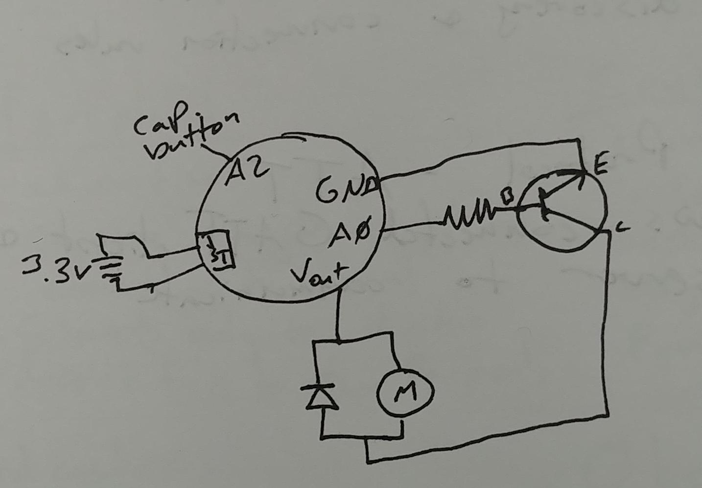
It’s relatively simple. The motor connects to the the Vout pin, which is always the max voltage the battery or USB can give, then to a transistor, then to ground. The transistor is acting as a switch. Its base is connected to A0, which will be controlled by the code. When A0 is high, it’ll “close the switch” aka let the transistor connect the Vout to ground, causing electricity to flow through the motor and vibrate. The JST bit is the JST connector on the Gemma. I’ll use that to connect to my coin cell batteries, and it’ll be the power when the bracelet is on my wrist. The “cap button” is the A2 pin, which I’ll use as a capacitive button, allowing me to cycle through the time between vibrations.
Future Danielle note: all of my planning writeups have 3.3V as the battery voltage. This is incorrect, as I explain later, but the rest is correct to the best of my knowledge
You’ll also see that diode sitting around, and it’s going the wrong way, to boot! I had to google around some to find a good answer for that, which I found at the Learning about Electronics website:
When driving a motor with a microcontroller such as the arduino we have here, it is important to connect a diode reverse biased in parallel to the motor. This is also true when driving it with a motor controller or transistor. The diode acts as a surge protector against voltage spikes that the motor may produce. The windings of the motor notoriously produce voltage spikes as it rotates. Without the diode, these voltages could easily destroy your microcontroller, or motor controller IC or zap out a transistor.
So that prevents accidentally killing the Gemma, which I aprove of.
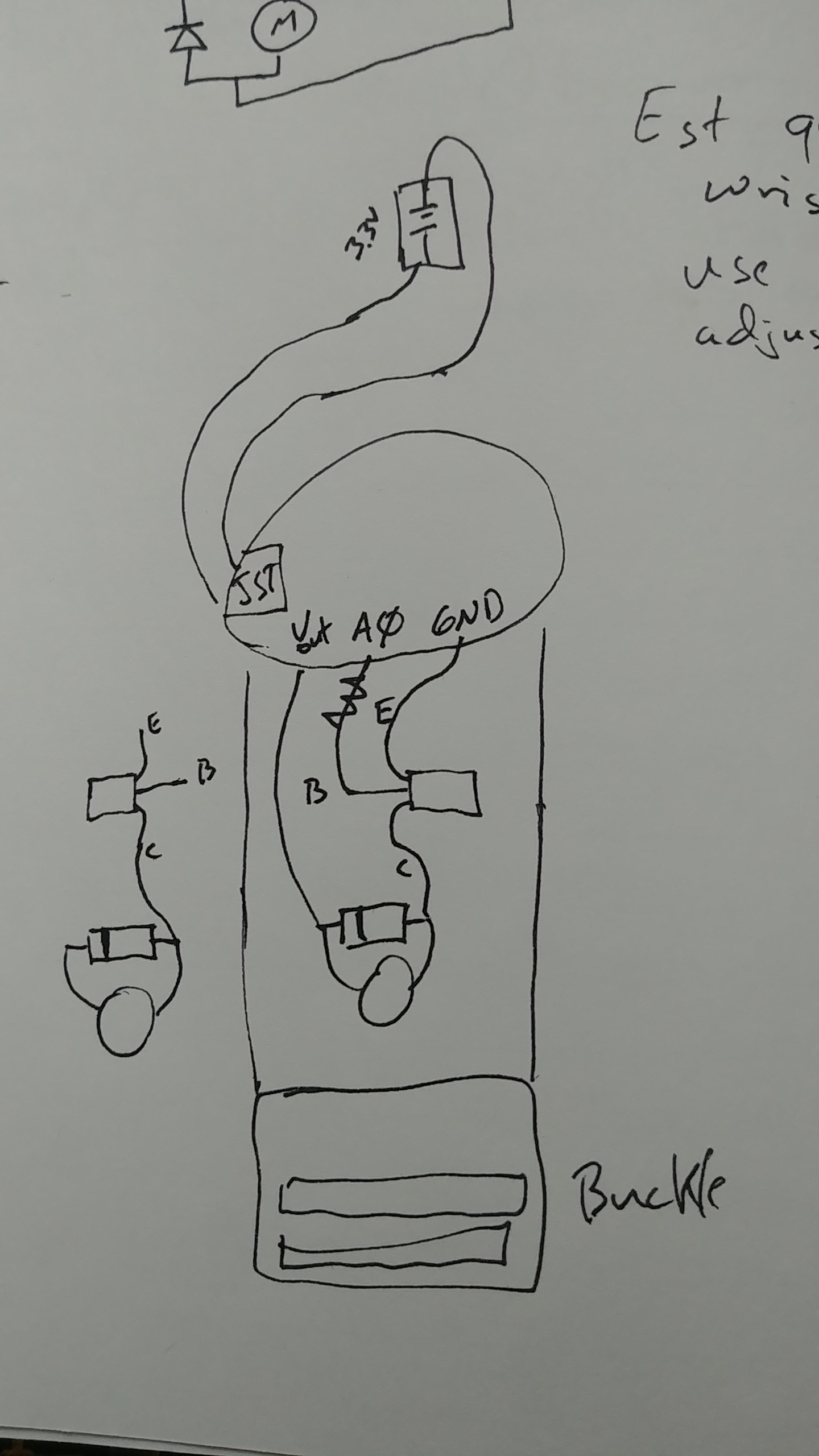
Now that I have a circuit planned, I have to figure out how to orient all the parts on the physical bracelet. I did a lot of drawing, but finally settled on a set up. Going from one side of the bracelet to the other, I’d have the vibration circuit, then the gemma, then the batteries. This way, I could have the vibration happen on the inside of my wrist, the gemma would be centered on the back of my wrist like a watch face, and the batteries would be out of the way of everything else.
The drawn version of what I mean:
Putting Things Together
This process is mainly where I remembered I don’t actually like hand-sewing that much, even though I can do it. There’s not much to say here, beyond I was simply following my planning, so this section is just a series of pictures of my work.
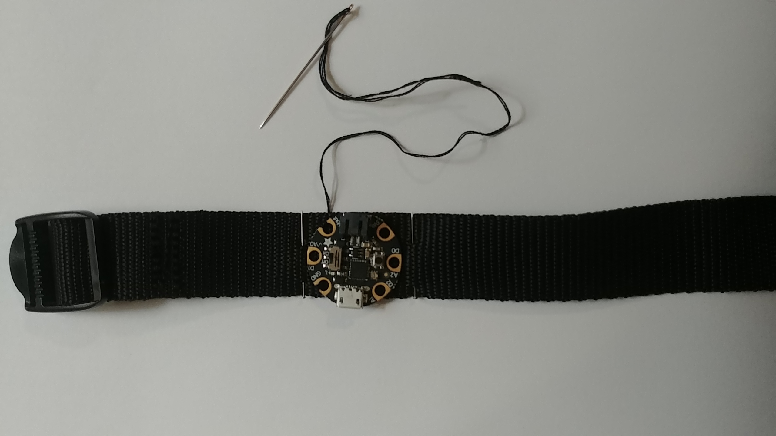
First step, I attach the Gemma to the nylon strap. I wanted to have it centered on the strap, so I put in two sewing pins to indicate where I wanted the gemma while the strap was on my wrist, then used those as reference when I sewed it on.
Now that it was on, I could orient the vibration circuit in the correct location and make sure my drawing was accurate:
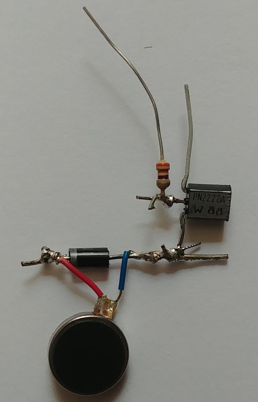
I then soldered together the vibration circuit:
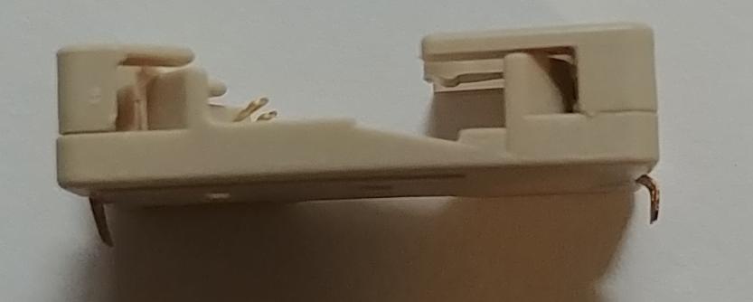
Everything seemed good for the vibration circuit, but before I spent too much time on that, I wanted to make sure the battery set-up would work. The battery holder is a bit too wide to fit crosswise on the strap, but I didn’t want it to go lengthwise because it would flatten out the nylon strip and make it harder to wrap around my wrist. So I ended up bending the connectors on the battery holder down, and then sewing it on crosswise. It’s still a bit bigger than I wanted, but it works!
The bent clips on the battery holder:
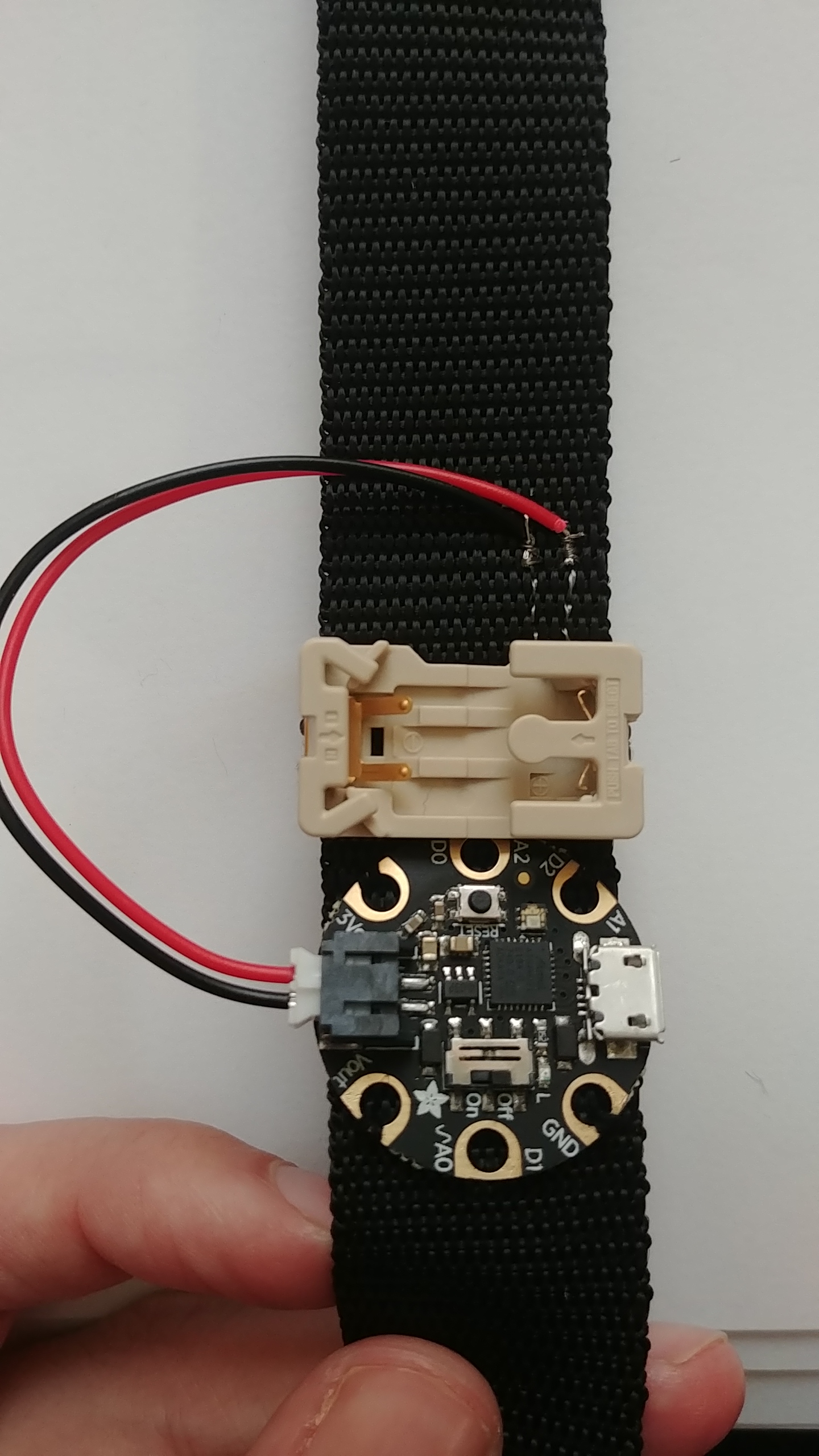
And this is with the sewn on battery holder and connection to the Gemma. You’ll note I’m only using one cell battery, when my hardware lists 2. Again, I’ll get to that in a bit. This is one of the places where I used my conductive thread! So instead of soldering the JST leads directly to the battery holder, I sewed the leads onto the strap, then used the conductive thread to attach to the battery. As a bonus, the thread helped the battery holder stay secure.
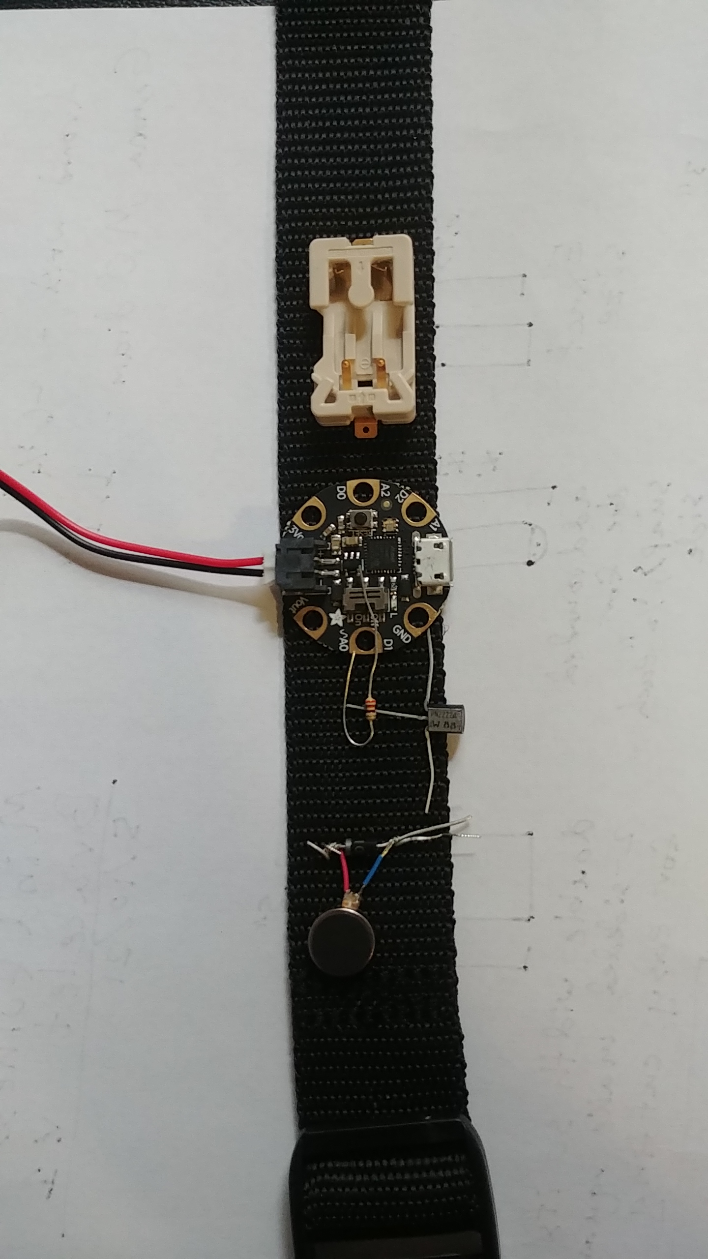
Lastly, I sew the vibration circuit onto the strap, and it’s completed!
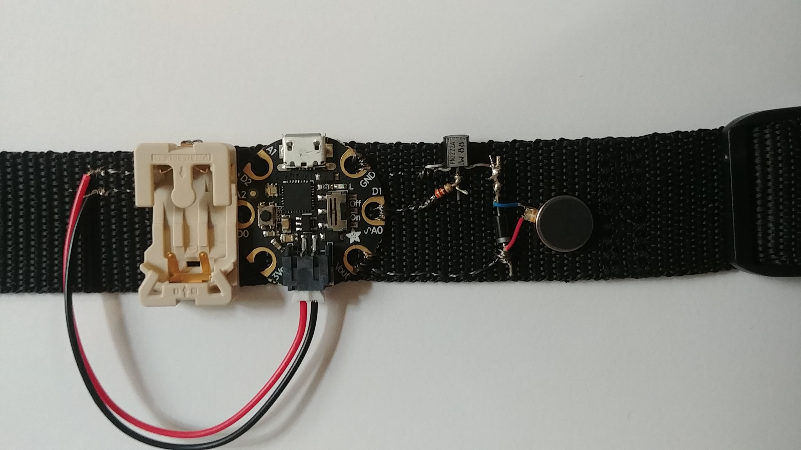
And a view on my wrist:
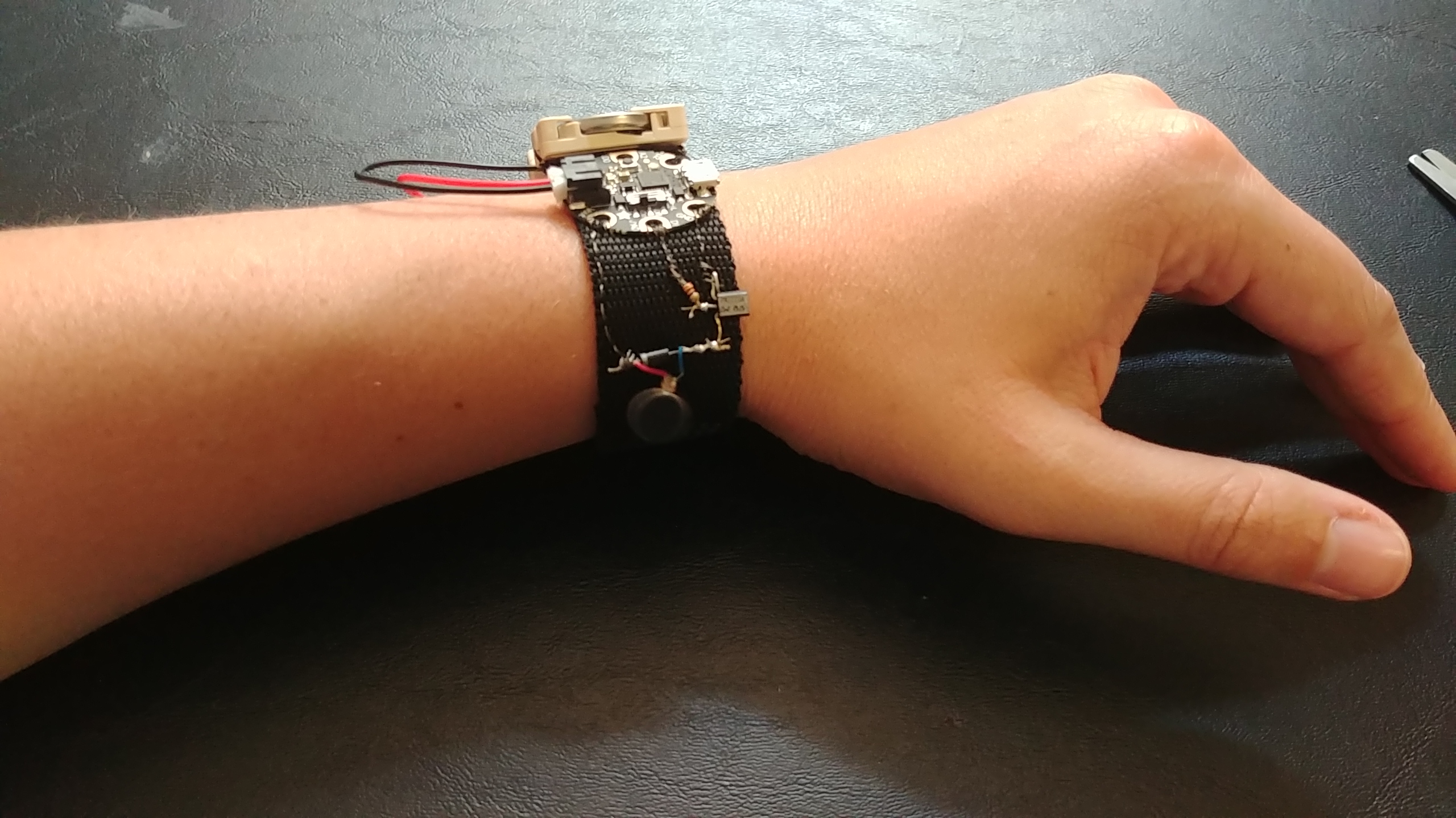
Now I’m ready to make it do stuff!
Software Side
The basic version of the software is available on the project page here: https://learn.adafruit.com/buzzing-mindfulness-bracelet/circuitpython-code. But where’s the fun of leaving things so simple! Let’s do some mods.
Future Danielle note: This is a good example of me forgetting the KISS principle - Keep It Simple, Stupid. While troubleshooting, I had to revert to the simpler version of the software repeatedly, because I didn’t fully understand the hardware side
Cycling Through Intervals
The first change is allowing users to change how long the Gemma waits between vibrations. There isn’t an easy way to let users type in a given number of minutes, but there are some capacitive touch buttons you can use. So I added the ability to cycle through a collection of times: 1 minute, 5 minutes, 10 minutes, and an hour. I attached cycling through these options to the Pad #0/A2 on the Gemma, setup as a capacitive touch button. And when the user changes the timing, they need to know what timing they’ve changed it to, so I need to inform the end user somehow.
So for this, add a check if the capacitive touch button is set to true, meaning the user is touching it. Then, I have to update the interval timing. Here’s that change in psuedo-python:
    on_time = 2     # Vibration motor run time, in seconds
    interval = 5
    intervalArray = [60, 300, 600, 3600] #interval options user can choose from
    intervalIndex = 1


    while True:

        # vibration turns on every interval seconds, for on_time seconds, non-blocking

        if touch cap button:
            intervalIndex = (intervalIndex + 1) mod len(intervalArray)
            interval = intervalArray[intervalIndex]
This lets me cycle through the array options, and once I get to the end of the array, looping back (that’s the mod bit)
NOTE mod, also represented as % means modulo, and it finds the remainder when you divide one number by another. E.g. if you divide 7 by 6 you’d get 1. A fun trick with modulo is that you can use it to keep an index value inside valid array indices without having to add
ifstatements. If an array is 0-indexed, you can always doindex = (index + 1) % arrayLengthand the result will always be 0 to arrayLength-1, exactly the indices you need!
Informing the User
Now, I can change the time between vibrations, but I need to tell the user what I changed it to. I have a dotstar LED on the Gemma that I can flash at the user. One flash per minute seems pretty reasonable. Since I was using the dotstar, I had to include libraries on the Gemma. Adafruit has pre-built libraries you can download here: https://learn.adafruit.com/adafruit-gemma-m0/circuitpython-libraries. You then copy the ones you need into the lib folder on the Gemma when it’s plugged into your computer. I ended up having to copy the adafruit_dotstar and pypixelbuf libraries. Look farther down under my “troubleshooting” section for an explanation of how I found the minimal required libraries.
So, the simple and naive version of informing users would be something like this (still in psuedo-python):
    on_time = 2     # Vibration motor run time, in seconds
    interval = 5
    intervalArray = [60, 300, 600, 3600] #interval options user can choose from
    intervalIndex = 1


    while True:

        # vibration turns on every interval seconds, for on_time seconds, non-blocking

        if touch cap button:
            intervalIndex = (intervalIndex + 1) mod len(intervalArray)
            interval = intervalArray[intervalIndex]
            # alert user of new time!
            for range(0 to interval/60):
                dotstar on
                sleep for .25 seconds
                dotstar off
                sleep for .25 seconds
Minimizing Sleep
If you write up the real python version of the psuedo code above and try it on your own project, you’ll see that it works! But there’s a bit of an issue there. It’s those sleep statements! If you do this, and say, set it to 10 minute intervals, that means the code is going to be in that for loop for 5 seconds. While it’s doing that, it’s not checking if it needs to vibrate or even change the interval again (say if a user wants to skip from 5 minutes to a half hour and skip the 10 minutes entirely).
NOTE How long the microcontroller takes for that
forloop is straightforward calculation. Each single time through thatforloop takes .25 seconds while the dotstar is on and .25 seconds while it’s off, for a total of .5 seconds per loop. Take that times the known 10 times it needs to flash equal 5 seconds. Now there’s also the time it takes for the dotstar to turn on and off, but it’s very likely the sleep calls vastly outweigh the time for the dotstar. Plus, the only way to speed up turning the dotstar on and off is to write my own dotstar library, but I can speed up by removing sleep calls much more easily.
So I need to update the code so it isn’t blocking while flashing the dotstar.
    on_time = 2     # Vibration motor run time, in seconds
    interval = 5
    intervalArray = [60, 300, 600, 3600] #interval options user can choose from
    intervalIndex = 1
    timesToTellUserAboutTiming = 0


    while True:

        # vibration turns on every interval seconds, for on_time seconds, non-blocking

        if touch cap button:
            intervalIndex = (intervalIndex + 1) mod len(intervalArray)
            interval = intervalArray[intervalIndex]
            timesToTellUserAboutTiming = interval/60

        if (timesToTellUserAboutTiming > 0):
            dotstar on
            sleep for .25 seconds
            dotstar off
            sleep for .25 seconds
            timesToTellUserAboutTiming -= 1
Adding a new global timesToTellUserAboutTiming variable lets me minimize how long the microcontroller is busy before it next checks if the cap button is touched. In this case, it will flash the dotstar once per while True loop, meaning the time between checking for button press is .5 seconds instead of potentially 5 or more. An order of magnitude of improvement, the best kind!
Now, if I wanted to get even LESS sleep, so it responds even snappier, I could add in interrupts or other fancier functionality. But by the time I got to this point in my project, I was starting to remember the KISS principle and left it as “good enough”.
Differentiating Hours and Minutes
This last step was a result of user testing (me, I was the user). While testing out button presses, I realized having the dotstar flash 60 times for hour intervals was just plain silly. I wasn’t going to count the flashes accurately past 10 or so, and it just took forever. So I decided to update the code one more time. This time, I updated it so that the color of the dotstar also carried info. If it was flashing blue, it was minutes, and green meant an hour.
    on_time = 2     # Vibration motor run time, in seconds
    interval = 5
    intervalArray = [60, 300, 600, 3600] #interval options user can choose from
    intervalIndex = 1
    timesToTellUserAboutTiming = 0
    newTimingColor = blue


    while True:

        # vibration turns on every interval seconds, for on_time seconds, non-blocking

        if touch cap button:
            intervalIndex = (intervalIndex + 1) mod len(intervalArray)
            interval = intervalArray[intervalIndex]
            timesToTellUserAboutTiming = interval/60
            newTimingColor = blue
            if timesToTellUserAboutTiming >= 60:
                timesToTellUserAboutTiming /= 60 # convert to hours
                newTimingColor = green

        if (timesToTellUserAboutTiming > 0):
            dotstar on with newTimingColor
            sleep for .25 seconds
            dotstar off
            sleep for .25 seconds
            timesToTellUserAboutTiming -= 1
This time, I check if the timesToTellUserAboutTiming is greater or equal to 60, which would mean it’s an hour or longer interval. If so, change the color to green. Otherwise, keep it blue.
Final Code
With all of the above steps, I came out with the final product below. Note that there’s certainly room for improvement, with some cleanup to make it simpler/easier to read. But again, in the spirit of KISS, and the fact I hadn’t figured out how to write unit tests for this, I didn’t refactor and left it at the version I knew worked.
    # Mindfulness Bracelet sketch for Adafruit Gemma.  Briefly runs
    # vibrating motor (connected through transistor) at regular intervals.

    import time
    import board
    from digitalio import DigitalInOut, Direction
    from analogio import AnalogOut
    from touchio import TouchIn
    import adafruit_dotstar

    debug = False

    #turn off the dotstar
    dotstar = adafruit_dotstar.DotStar(board.APA102_SCK, board.APA102_MOSI, 1)
    dotstar.brightness = 0
    dotstar.fill((0, 0, 255))

    # vibrating disc mini motor disc connected on D2
    #use as an analog out so can control how much the motor vibrates
    vibrating_disc = AnalogOut(board.A0)
    # quarter power: 16384
    # half power: 32768
    # full power: 65535
    # NOTE: the vibration amount depends on voltage in. If powered by USB,
    # quarter power is about right. If powered by a single 3V watch battery,
    # full power is the way to go
    vibrating_disc_on_value = 65535


    # Built in red LED
    led = False
    if debug:
        led = DigitalInOut(board.D13)
        led.direction = Direction.OUTPUT

    # Capacitive touch on A2
    touch2 = TouchIn(board.A2)

    on_time = 1     # Vibration motor run time, in seconds
    interval = 5   # Time between reminders, in seconds
    intervalArray = [60, 300, 600, 3600] #interval options user can choose from
    intervalIndex = 1
    timesToTellUserAboutTiming = 0
    newTimingColor = (0, 0, 255)

    # Updates the number of flashes it needs to display to tell the user
    # how many minutes between vibrations it has just been set to
    # does not actually flash the LED in this function, instead uses tellUserNewTiming()
    # to avoid sleeping and potentially missing more input and/or time to vibrate
    def setNewTiming():
        global interval, timesToTellUserAboutTiming, newTimingColor
        interval = intervalArray[intervalIndex]
        timeInMinutes = interval/60
        newTimingColor = (0, 0, 100) # blue

        timesToTellUserAboutTiming = timeInMinutes

        if timeInMinutes >= 60:
            timesToTellUserAboutTiming = timeInMinutes / 60
            newTimingColor = (0, 100, 0) # green
        time.sleep(.3) #make sure it's clear a new time is being set

    # Checks if the dotstar still needs to flash to tell user about a newly set time interval
    # between vibrations. If there's still flashes needed, it will flash and sleep
    def tellUserNewTiming():
        global timesToTellUserAboutTiming
        if (timesToTellUserAboutTiming > 0):
            #turn on for a short time
            dotstar.brightness = .2
            dotstar.fill(newTimingColor)
            time.sleep(.25)
            #turn off for a short time
            dotstar.brightness = 0
            dotstar.fill(newTimingColor)
            time.sleep(.25)
            timesToTellUserAboutTiming -= 1


    def initialSetup():
        #buzz some so you know it's awake!
        vibrating_disc.value = vibrating_disc_on_value
        time.sleep(.10)
        vibrating_disc.value = 0
        time.sleep(.10)
        vibrating_disc.value = vibrating_disc_on_value
        time.sleep(.10)
        vibrating_disc.value = 0
        time.sleep(.10)
        setNewTiming()


    initialSetup()
    interval = intervalArray[intervalIndex]

    start_time = time.monotonic()

    while True:
        timer = time.monotonic() - start_time

        if timer >= interval and timer <= (interval + on_time):
            vibrating_disc.value = vibrating_disc_on_value
            if debug:
                led.value = True
        elif timer >= (interval + on_time):
            vibrating_disc.value = 0
            if debug:
                led.value = False
            start_time = time.monotonic()

        # use A2 as capacitive touch to cycle through interval options
        if touch2.value:
            intervalIndex = (intervalIndex + 1) % len(intervalArray)
            setNewTiming()

        tellUserNewTiming()
Troubleshooting Software
Partway through my development, I somehow managed to reset the Gemma completely. It removed my code and libraries, and set it back to the default example it shipped with. I have no idea why. But happily (kind of),that meant I got to learn how to troubleshoot the Gemma some!
When it was reset to default, I first copied my code over. And then it just started blinking at me. As it turns out, adafruit includes a way of troubleshooting your code on the Gemma using just the dotstar. Their documentation here: https://learn.adafruit.com/adafruit-gemma-m0/troubleshooting, explains what different flashes mean.
Colors with multiple flashes following indicate a Python exception and then indicate the line number of the error. The color of the first flash indicates the type of error:
GREEN: IndentationError
CYAN: SyntaxError
WHITE: NameError
ORANGE: OSError
PURPLE: ValueError
YELLOW: other error
Once that happened, I knew I needed to connect to the REPL so I could see the error there. I’m on linux, and so used https://learn.adafruit.com/welcome-to-circuitpython/advanced-serial-console-on-mac-and-linux to get me to connect.
I ended up using this to connect with repl and see the error:
screen /dev/ttyACM0 115200
And the first error was:
main.py output:
Traceback (most recent call last):
File "main.py", line 9, in <module>
ImportError: no module named 'adafruit_dotstar'
Ah! Since it was set to default, the libraries I had it in were gone. So I re-downloaded the libraries and copied over the adafruit_dotstar library. Now, I got a different error:
main.py output:
Traceback (most recent call last):
File "main.py", line 9, in <module>
File "adafruit_dotstar.py", line 22, in <module>
ImportError: no module named 'adafruit_pypixelbuf'
Getting errors one at a time like this is kind of annoying. But! I copied over the adafruit_pypixelbuf library as well, and the code worked. Yay!
Putting it all together
I now have the code! I now have the hardware! Now the big step, load up the code, then disconnect the USB and power it by battery!
…why is it suddenly blinking brown at me?
I restart it, same issue. I connect to USB, it works!
Hmmm. The biggest difference there is amount of power it gets. Uh oh, I may be misunderstanding some things…
Aside: Understanding Battery Calculations
I haven’t had much reason to learn battery calculations, aka figuring out what type of battery I need and how long they’ll last. I was a web developer previously, if your laptop dies while you’re looking at my site, that’s a you problem. But now, it was very much my problem!
Initially I had only one coin battery on my bracelet, leading to what I believe were brownouts, where the voltage dipped too low to support everything, and the microcontroller just complains at me. Since plugging it into USB works, I figure I need more juice. After double checking the adafruit docs, it turns out it needs 4-6 Volts.But one coin battery is 3.3. Why then does the initial project have a 3.7V battery? No idea. But let’s see if I can hack something together. I remember you can increase voltage by connecting batteries…somehow. Some googling proved I can connect two coin batteries in series to increase the voltage amount: https://www.power-sonic.com/blog/how-to-connect-batteries-in-series-and-parallel/. I do this by connecting the negative terminal on one to positive of the other. The free positive and free negative attach to the microcontroller. I used the multimeter to check the voltage before I connect to the microcontroller, and it was 5.98V, which was perfect! I gave it a whirl, and it works! But the thing is, I wasn’t entirely sure why. I googled around more, but only got more confused.
I took to the local makerspace’s slack, and got some lovely people to explain the concepts to me. After talking through my project and some general guidelines for calculating battery things, I came out with the following.
For figuring out voltage needed I go through all the parts in my circuit and figure out their voltage range (i.e. look at the docs). I then make sure the voltage I provide is either inside the range of all parts, or add a part that changes the voltage before it gets to the sensitive bits, so nothing blows up.
For figuring out how long the batteries last for a circuit I haven’t built yet I’d take all power-hungry parts in the circuit, add up their current usage, make sure it’s the same units as the battery’s hour unit (e.g. make sure it’s mA if the battery has 200mAh), and divide the mAh by the summed up mA (plus a bit for fudge factor), and that gives me a rough time it’ll live.
For figuring out how long the batteries last for a circuit I have built use a multimeter in series with the circuit, make sure I use the right setting to prevent tripping the fuse, and it’ll show me the current current (har har) usage. Then divide the battery mAh by the current I see on the multimeter, and I get the rough time it’ll live.
Battery Calculations for the Bracelet
Since I have this newfound knowledge, let’s put it to good use! First step: figure out voltage. I do that by looking at all parts of my circuit, and reading their docs. My schematic-reading abilities came in handy for this, because the Gemma M0 is a microcontroller, plus other parts, so I couldn’t just rely on knowing the microcontroller and going from there. Happily, Adafruit puts out the schematic info, so I could look at it, and then google part numbers to find out what each part did.
The Gemma M0 is broken down into individual parts as understood from schematic here: https://cdn-learn.adafruit.com/assets/assets/000/044/361/original/gemma_schem.png?1501106076. I also include the vibration motor, the only other power-hungry part in my circuit.
| part No. | Part Type | voltage range | current use | Datasheet |
|---|---|---|---|---|
| ATSAMD21E18 | 32-bit ARM Cortex -M0+ processor | 1.62V – 3.63V | 3.11 - 3.64 mA | https://cdn-learn.adafruit.com/assets/assets/000/044/363/original/samd21.pdf?1501106093 |
| ap211k-3.3 | CMOS process low dropout linear regulator | 2.5V-6.0V | 55µA when quiescent aka .055mA | https://www.diodes.com/assets/Datasheets/AP2112.pdf |
| AP102-2020 | APA102 IC for the three-color RGB Dimming control strip and string | .3-6V | .1W-.5W aka 20mA-100mA according to this watt to amp calculator | https://cdn-shop.adafruit.com/product-files/3341/3341_APA102-2020+SMD+LED.pdf |
| 100614 | Vibration motor | 2.5~3.8V (adafruit site says 2V - 5V) | 75 mA max (adafruit site has a larger range depending on voltage, from 40mA-100mA) | https://cdn-shop.adafruit.com/product-files/1201/P1012_datasheet.pdf |
Voltage Calculation
Looking through all of this, the voltage needs to be between 2.5 and 6 volts. And the vibration motor needs only 5V. Right now, it’s connected to Vout, which is supposed to be the max power the Gemma M0 is receiving. So it may actually be getting 5.98V right now. Since it hasn’t blown up yet, it must be able to handle that, but I may need to update how that connects so I don’t prematurely wear it out.
Current calculation
For the parts that are potentially running all the time, I just need to get the max current use for each of them, aka the SAMD21 and the linear regulator.
For the vibration motor, because I’m turning it on and off for brief time periods, I don’t want to just add the current it uses when on to the total amount, because it’s only on for short times. So I need to calculate the duty cycle (percentage of time it’s pulling current over a given cycle). So if it buzzes for one second every minute, that’d be 1/60, aka it’s on 1.66% of the time. So if it’s drawing 100mA cuz I’m giving it 5V, that means on average it’s drawing 100mA*(1sec/60sec), aka 1.67mA.
NOTE Duty cycle is the percentage a part is on and drawing power, for a given cycle
I have to also do this for the IC that controls the dotstar LEDs (part no. AP102-2020 in above table). This one has a max of 100mA current as well. In code, I’m turning on LEDs for a quarter of a second, to display info to end users. To keep it simple, I’ll pretend the user wants to change the interval timing every 10 minutes. If it’s flashing the max times (10 times for 10 minutes), then it’ll be on for 5 seconds every 10 minutes. Or 5/600, aka 0.00833, or .83% of the time. That means it’s average current use is about .83mA
Current use (taking the max current usage for some leeway) is:
(max current of SAMD21) + (max current of linear regulator) + (average current of dotstar RGB IC) + (average current of vibration motor)
=3.64 mA + .055mA + .83mA + 1.67mA
=6.195 mA
If the battery is 220mAh, then with this circuit, the batteries will last 220mAh/6.195mA = 35.51251008 hours
Cool! That’s certainly not a ton of time, since this would theoretically be on all day, but it’s still way more than I expected. I honestly figured with my luck the math would work out to be an hour or something.
Now, I wanted to verify all this math with some measurements using my multimeter. I go to try, and….the Gemma errors out on me. I reset it. Same thing. Welp. Guess I won’t be solving this in this blog post! And I was so close!
Before I tried to do the battery calculations, I had actually test-driven the watch. I wore it for a half hour or so, and it worked great! My suspicion is that something is using more power than I think, and it’s draining the batteries. But I’ve used up all my coin cell batteries already, so I won’t be able to probe the circuit with the multimeter to find the high power usage! I’ll have to pick up more batteries next time I’m at the store, and try again then. But for now, I think this blog post has come to an end. Not the triumph I had envisioned, but a hard-fought battle with a lot of new concepts.
Conclusion
This project was a lot more work than what I thought “a simple embedded project” should be. But I learned a lot more about:
- troubleshooting with multimeters
- transfering a circuit schematic from a drawing to real-life
- how to calculate battery life
- coming up with alternative ideas to communicate to users
- the importance of avoiding sleep (the function, not the real-live version)
Which was honestly the goal, more than a working mindfulness bracelet. I’ll continue working on this, and hopefully figure out the latest issue, and post talking about that. I may also look into transferring my functionality from CircuitPython to C and see if I can get that onto the Gemma.
Ultimately I think the defeat was mainly from biting off more than I can chew (aka forgetting to KISS). Making my first custom embedded project use batteries made it a lot more complicated that it would have been otherwise, and modifying the battery I use for it was definitely a mistake. Learning things is best done using +1 steps, learning just one new thing each time, but I was too excited and tried about a +10 instead.
I haven’t given up on this project yet, but I may let it sit back burner as I work on other projects. I finished a unit testing course that I want to apply to a project, and I want to do more STM32 work. The frustrations of this mindfulness bracelet have defeated me for now (which is more than a little ironic), but not forever.
Resources
The original project: https://learn.adafruit.com/buzzing-mindfulness-bracelet/overview
This troubleshooting page explains any blinking dotstar errors you may come across: https://learn.adafruit.com/adafruit-gemma-m0/troubleshooting
Follow this to connect with repl and see errors when the Gemma is attached to your computer: https://learn.adafruit.com/welcome-to-circuitpython/advanced-serial-console-on-mac-and-linux
Learning about Electronics website http://www.learningaboutelectronics.com/Articles/Vibration-motor-circuit.php