Getting started with STM32 black pill - Getting blinky with STM32Cube IDE
Now that I’ve dipped my toes into the microcontroller world, lets cannonball in with the world of STM32 microcontrollers. There’s a ton of different microcontrollers that are all STM32, but I’ll be starting with a relatively easy starting microcontroller. It’s easy because it comes on a cheap development board that doesn’t require any custom PCB work, and it has a funny nickname. I’m talking about the We Act Studio’s STM32F411 dev board, nicknamed the “Black Pill”. It lets me start figuring out the embedded toolchain immediately, without having to dive too deep into the hardware side. Though I’ll still be looking at schematics, since they’re important and it’s good practice.
The company that makes STM32 microcontrollers is called STMicroelectronics, though later in this post I’ll just refer to them as ST. And happily, they have developed a lot of software and support for the STM32, so hopefully, it’ll be a pretty easy process to ge the toolchain set up.
Going back to the Embedded For Everyone wiki https://github.com/nathancharlesjones/Embedded-for-Everyone/wiki/1.-Getting-to-%22Blinky%22-with-a-new-MCU, there’s a nice graphic that shows all parts of an embedded system toolchain. AKA all the bits needed to actually program and debug a microcontroller. I annotated it with what I’m going to use, to give kind of an overview of my whole toolchain.
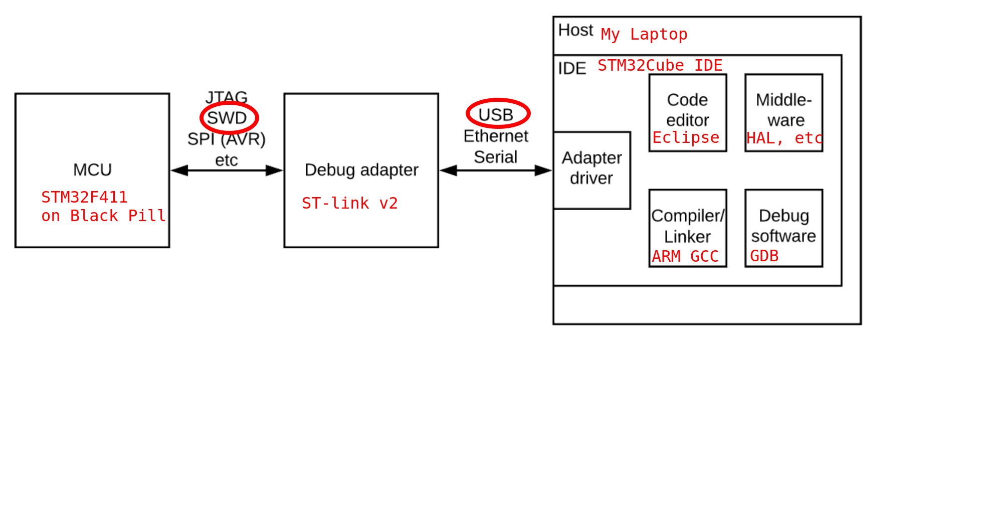
Lets go a little more in-depth about these pieces.
- The MCU - this is the STM32F411 microcontroller that is on the Black pill board
- Serial Wire Debug (SWD) - I’ll talk to it via the SWD header that’s on the Black pill board
- Debug adaptor - this is the ST-link v2. It connects to the SWD header on the black pill, and has a USB plug to let it talk to the computer. Everything after this in this list is software. The only bits of hardware needed are the Black pill and this ST-link v2!
- The IDE- this contains all the software and packages I need to talk to the black pill. I’ll be using the STM32Cube IDE. It contains the following sub-systems
- Adaptor Driver - this talks with the st-link v2 via USB. It can send code (aka the ST-link is a programmer), and can also talk with the MCU directly to do debugging(so the ST-link is also a debugger). It supports both the ST-link v2, and also J-link, an alternative debugger hardware.
- Code Editor - this is the actual place I write my code. It’s based on Eclipse, a popular IDE, and according to ST’s website, can support Eclipse plugins
- Middleware - this is all the code written by ST to make programming STM32 microcontrollers easier. ST calls them STM32cube MCU/MPU packages. These include the Hardware Abstraction Layer (HAL), Low-Layer (LL) APIs, and various libraries to support things like Real-time operating systems (RTOS), USB, file systems, etc. It also has a GUI that helps you with your initial setup of the different pins of a microcontroller. E.g. setting a particular pin to be a GPIO output pin. The STM32Cube IDE has packages for each of the STM32 families it supports. It’s a lot of code
- Compiler/linker - this is the ARM GCC toolchain. This is the bit that actually compiles your C code into something the STM32 ARM microcontroller can actually run
- Debug software - the STM32Cube IDE supports using GDB as the debugger, which is a common C debugger tool. It also has extra debug support, like supporting RTOS debugging.
The Hardware Side
There’s apparently a lot of places to get the hardware side, and for relatively cheap. But a lot of the places seem to be “Aliexpress” and “Ebay”, and it feels like the quality control and speed of delivery for those both can be lacking. So instead, since I buy so much from Adafruit anyway, I decided to get my software from there.
As I mentioned above, I only need two bits of hardware, the black pill itself, and the debugger/programmer ST-link. The ST-link even comes with the right female-to-female jumper wires so I can connect the two together. Below are the links to adafruit for the hardware I had to order.
- ST-link V2 from adafruit: https://www.adafruit.com/product/2548
- We Act Studio STM32F411 “BlackPill” Development Board https://www.adafruit.com/product/4877
Once I got them, I need to connect them together. The black pill from adafruit comes with header pins that aren’t soldered on, so I had to do some light soldering to get the SWD pins and the header pins connected up.
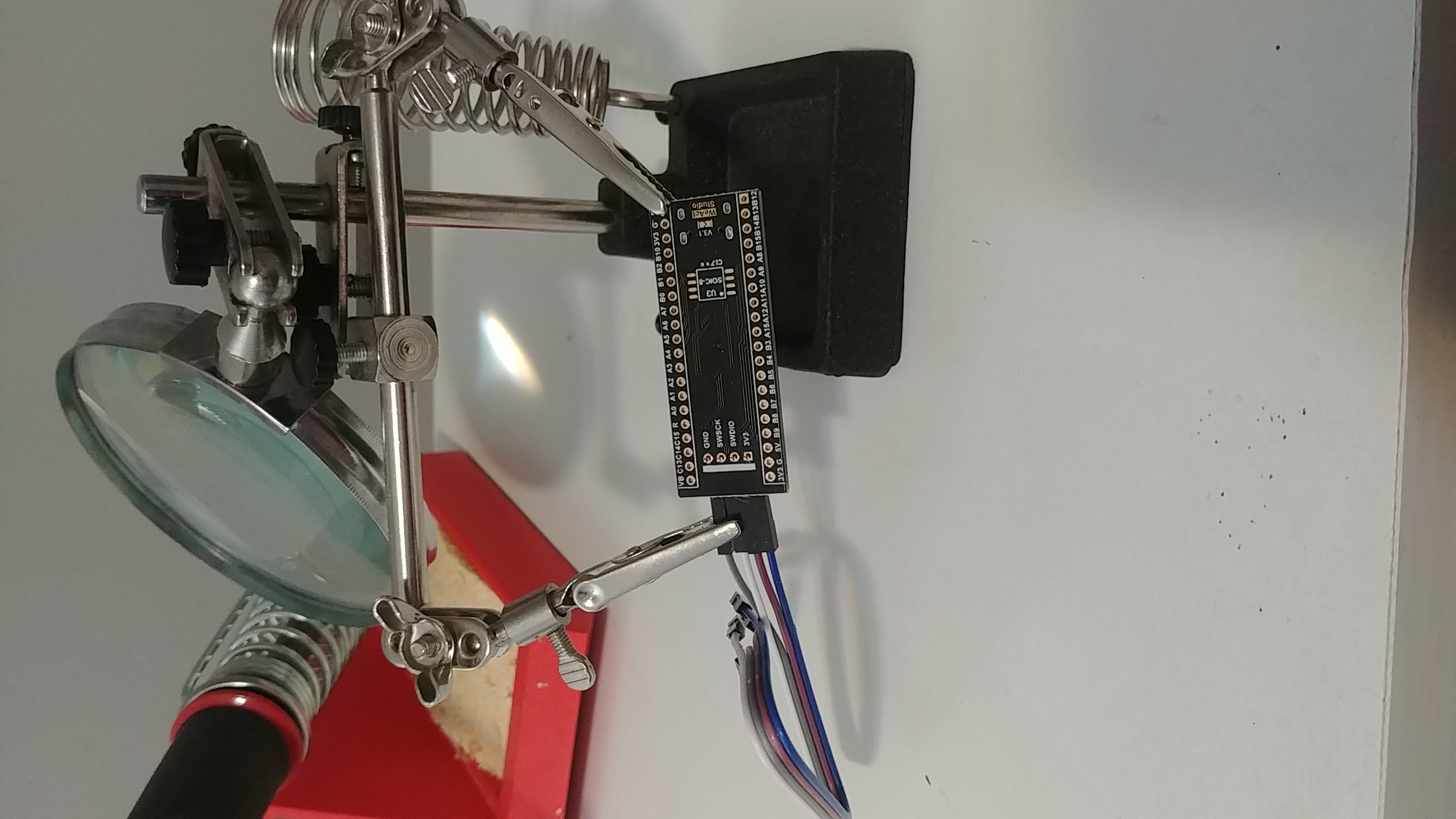
I used my third hand to keep the board and SWD header pins steady while I soldered it up. I also attached the female jumper wires to the SWD pins, to make sure I didn’t solder the pins too close to the PCB board. After I this, I soldered on the headers that run down each side of the black pill, and used the trick of attaching it to a breadboard, so the pins are properly straight while I solder.
With the pins all on, I need to connect the st-link and the black pill together. Happily, the st-link v2 has the pinout for its connections right on it’s casing, so I don’t need to lookup the pinouts online. The black pill has what each SWD header pin is connected to screenprinted on the board as well. So it’s a matter of connecting the included female-to-female jumper cables to the correct pins on each. They each call the pins something slightly different, but it’s pretty easy to guess which goes to which. Since this is SWD communication, you just connect each pin that’s named the same together. This is different than more tricky connections, like UART, which requires you to connect the Rx pin to the Tx of the other device and vice versa.
Here’s a table of the pin connections from the Black pill to the st-link. They’re in order for the black pill’s pins from top to bottom if the SWD header is facing to the right. I list the wire color because that’s helpful to track when you’re connecting them together, but the wires are not different in any way beyond coloring.
| Black Pill Pin | Wire Color | ST-link pin |
|---|---|---|
| GND | Grey | GND |
| SCK | Blue | SWCLK |
| DIO | Purple | SWDIO |
| 3.3V | White | 3.3V |
And below is a picture of the final connection.
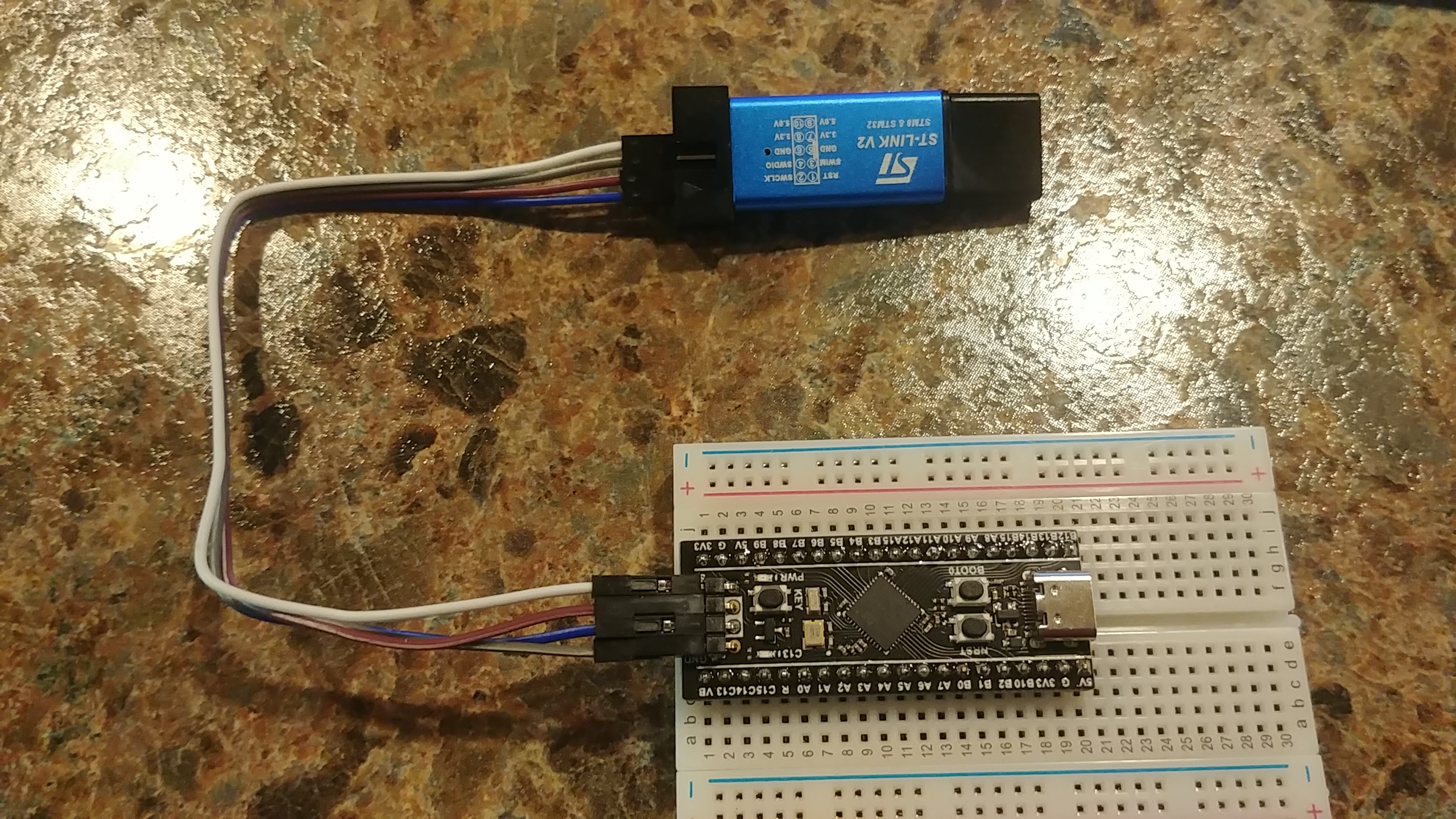
Once connected, I plugged the ST-link’s USB into my computer, and success! No magic smoke escaped, and the power button lit up on the black pill. It’s now ready to program.
The Software Side
I’m using the STM32Cube IDE, which is nice because it’s all in one package to download. Download the IDE from: https://www.st.com/en/development-tools/stm32cubeide.html. There’s a version for Mac, Windows, and Linux.
I haven’t used this IDE package much yet, so I can’t give a recommendation on it one way or another. From what little I’ve done on it, it feels very much the classic “you can do everything here, but first you have to find the button for it” sort of IDE that’s very popular. E.g. Visual Studio, Eclipse, Netbeans, that sort of thing. There’s a lot of useful functionality, but it comes at the cost of complexity.
Also, because it’s based on Eclipse, which is Java-based, it can be pretty hefty and a bit of a strain on your system. I’ve already had issues with it hanging on my laptop. I’m not sure if this is because I’m running the Linux version, and it’s less supported than the windows/mac versions, or if it’s a common symptom of the STM32Cube IDE in general, or my computer just doesn’t like linux. Regardless, I had to get a book out to read while the IDE thought about various steps in my intitial set-up.
My eventual plan is to build out a more light-weight toolchain, potentially using docker to wrap all the dev tools up in one location. I liked the ATmega328p toolchain, that just used the compiler and avrdude to send to the chip, and I’d like to build out a similar toolchain for the black pill. But until then, let’s move on to writing some code.
The Code
Since I’m using ST’s recommended software, and it has everything but the kitchen sink, most of the work getting this project set up is clicking things inside the GUI. If I create a new project and tell the IDE what MCU I’m using, it will auto-generate all the setup code needed for me. So instead of adding in headers and setting individual pins to output, I just click on things.
Setup Steps
- Open up STM32Cube IDE, select File -> New -> STM32 Project
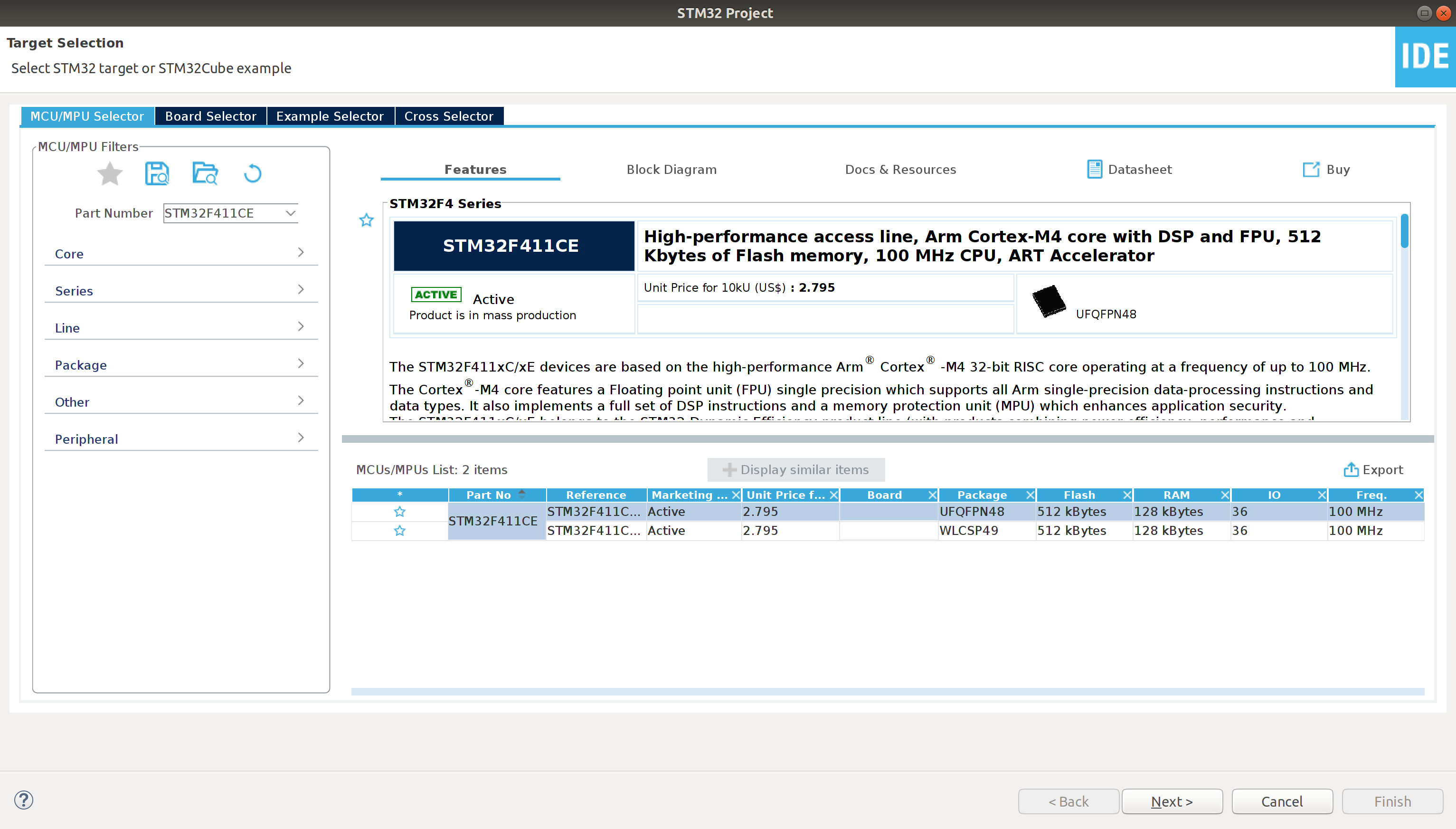
- In the MCU/MPU Selector, enter “STM32F411CEU” into the search. This is the full name of the MCU on the adafruit black pill board. Select the only result in the search results, and click next
- In the project setup popup, set the project name (In my case, I chose “Blinky”), leave the rest as default, so click next, then finish.
- Once that’s done, it will open up the pinout and configuration page. There it’ll display the physical shape of the MCU, and the pins and pin names. This is where you can set individual pins to different default values, and the IDE will use this info to auto-generate setup code. In our case, we want to just left-click the
PC13pin, and click “GPIO_Output”. This pin is the pin connected to a user-controlled LED on the black pill. If you look on the black pill, you can see the LED we want to control, and see it hasC13next to it. Eventually we can set other pins to use more of the black pill’s dev board, but for now, that’s all we need to make blinky run.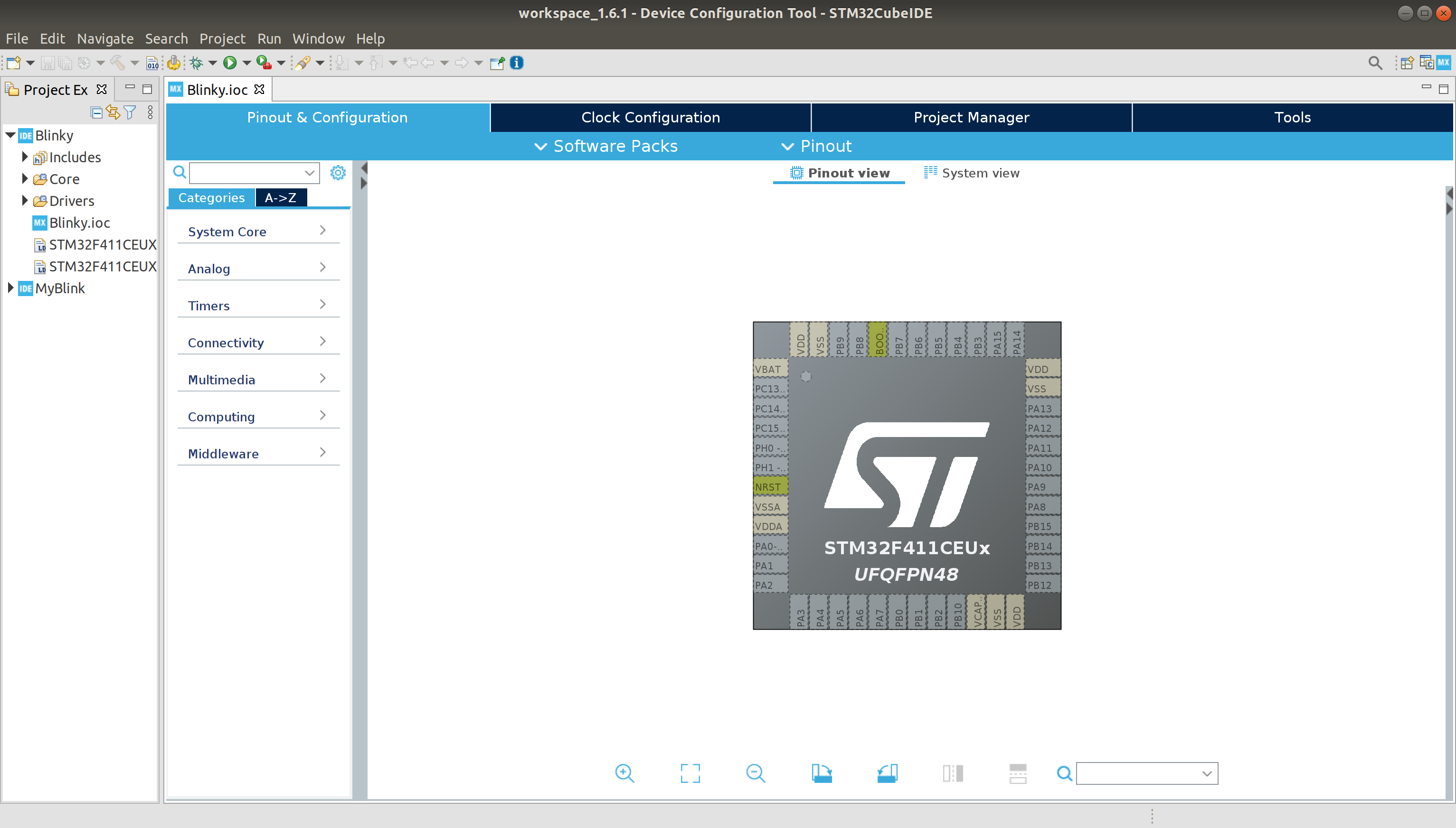 MCU configuration page
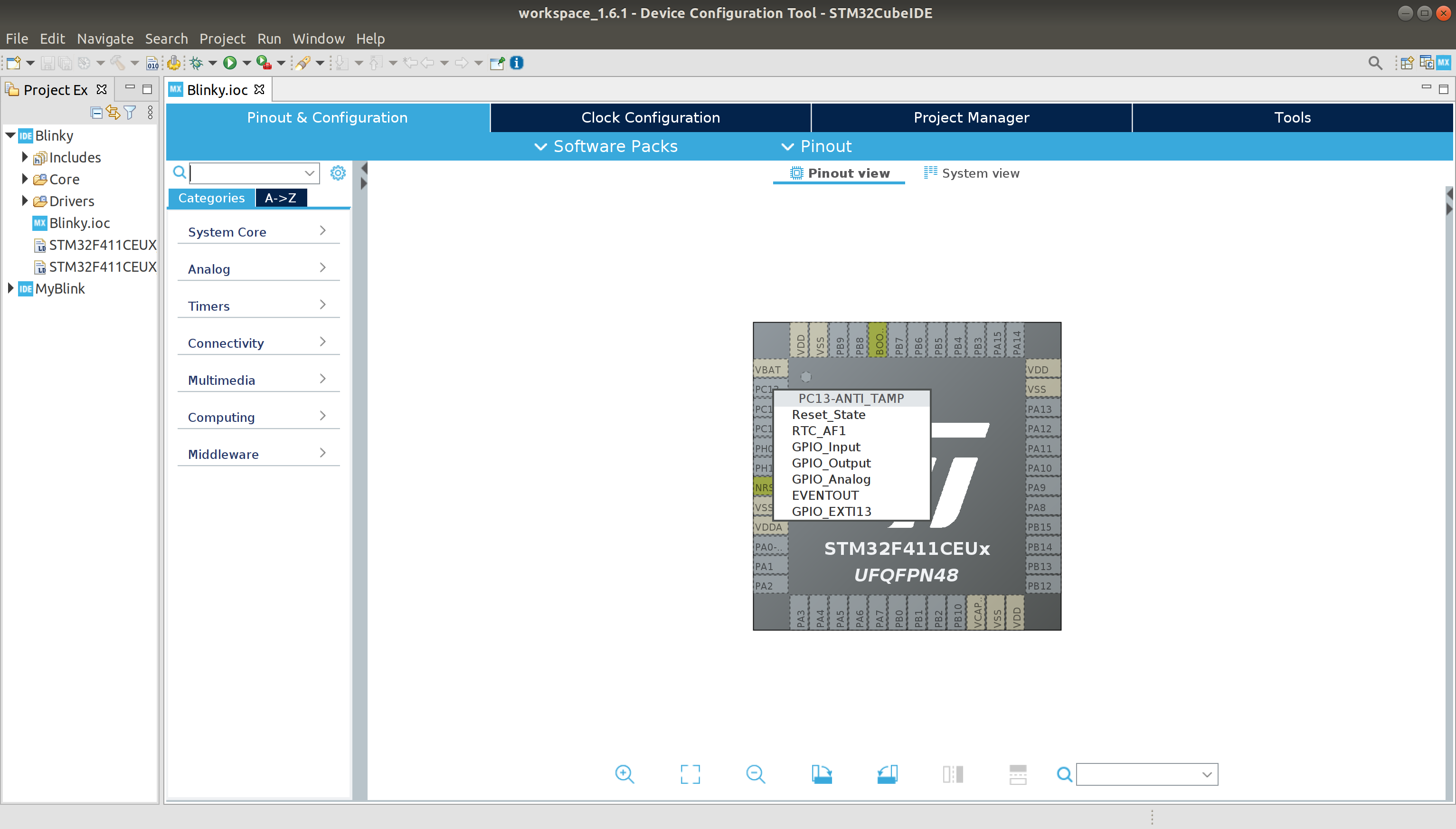 Left-clicking the PC13 pin
 What the MCU configuration page looks like when PC13 is set to output
 - To have the IDE generate code, click the save icon, or hit
ctrl+sto save the configuration. It will ask if you want to generate code, and then ask if you want to open the code perspective. Click yes to both. - Now the main.c file will be open in one of the tabs. Select it. This is finally some C code!
- Scroll down to the
while(1)section. This section is equivalent to theloop()function in arduino. Here we can add our code to turn thePC13pin on and off.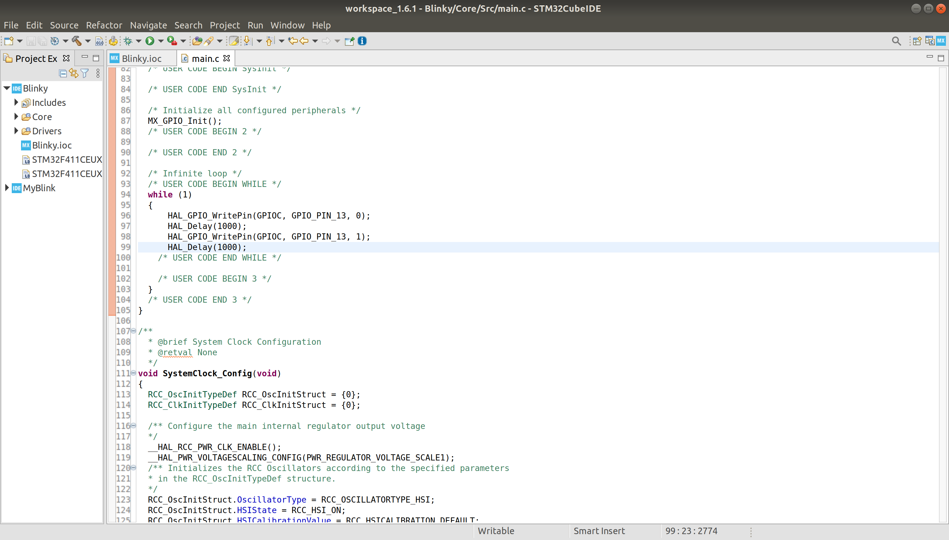
Oof that’s a lot of clicking before we can even write a single line of C code! But we’re finally here. Now last time, with the ATmega328p, I didn’t use any libraries, and instead directly referenced registers in memory and did the appropiate bit-twiddling to get it to change the pin I needed. This time, I’m going the more “proper” way, and actually using libraries. Libraries let you abstract out specific implementations of different functionality, making your code (arguably) easier to read, and more portable. In this case, I’m using ST’s Hardware Abstraction Library (HAL), to set my pin to low, wait a second, then set it to high.
The calls I need to make are to HAL_GPIO_WritePin() and HAL_Delay(). The HAL_GPIO_WritePin function takes which register (in this case, C), which specific pin (13), and if I want it high or low (0 or 1). The HAL_Delay acts similar to the arduino delay function, and accepts a number, in milliseconds, of how long to delay.
NOTE I belive that comment on
HAL_Delayis not technically true. I left the default clock settings, so the MCU is running at that speed. I suspect theHAL_Delayis not timing it to milliseconds, but rather to clock cycles. I haven’t confirmed this, however. And treating it as milliseconds-ish seems to work well enough for a blinky example
Using this info, I can type in the main.c file and finally have my blinky example! STM32Cube IDE has auto-complete that lets me type my (very little) code faster, you can use it by starting to type a function, then ctrl+space to open the auto-complete options. Use the arrow keys to tab down the list, and click enter when you’re on the function you want.
NOTE The code you write should be between comments in main that say
USER CODE BEGINandUSER CODE END. These comments let you know where to write your custom code, while still being able to use the MCU configuration to auto-generate code. If you want to change or add pin configurations in the MCU configuration page, any code written between a user code begin and end will be kept, but anything outside those comments will be overwritten. There’s a lot of different user code sections throughout themain.cfile, so any custom code you want can be written wherever you’d like.
Final code
So the final code inside the while loop, for a simple blinky using the STM32CubeIDE with the We Act STM32F411 “black pill”:
 while (1)
  {

	  HAL_GPIO_WritePin(GPIOC, GPIO_PIN_13, 0);
	  HAL_Delay(1000);
	  HAL_GPIO_WritePin(GPIOC, GPIO_PIN_13, 1);
	  HAL_Delay(1000);
    /* USER CODE END WHILE */
    /* USER CODE BEGIN 3 */
  }
Note that I’m setting pin 13 to 0 to turn it ON, and 1 to turn it OFF. If you don’t believe me, try changing the delay after the first WritePin to 5000 and see if it stays on or off longer. This is a result of how the LED is wired on the black pill board. If you look at the schematics for the board, you can see that the LED circuit is actually connected to 3.3 volts, then a resistor, then the LED, then PC13. This means when PC13 is low (set to 0), it acts as ground, and electricity moves through the circuit.
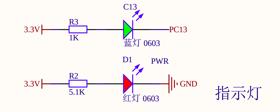
This is a screenshot of the schematic diagram that adafruit gives here: https://cdn-shop.adafruit.com/product-files/4877/4877_schematic-STM32F411CEU6_WeAct_Black_Pill_V2.0.pdf. It shows two LEDs, the bottom one is the power LED, and other is the user-controlled LED on pin 13.
As an aside, since a lot of hardware comes from China, I kind of wish I was learning Chinese as well as Japanese, so I could read their data sheets easier! Always more to learn, never enough time…
Sending the code
Finally, everything is coming together! Now that the STM32Cube IDE is all set up, we need to actually send the code to the black pill. This is happily, very easy. Plug in the ST-link v2 to your computer, make sure it’s connected to the black pill (the power pin should turn on), and click the green right arrow in the IDE. This will open the build configuration. You can leave that as default and click next. And it should send the code over!
Firmware updates
When I attempted to do this the first time, STM32Cube IDE popped up a warning the firmware on my ST-link v2 was out of date and asked me to update it. I’m easily swayed by pop-up messages, so I did. Since nothing seemed to break from me doing that, I recommend allowing it to update.
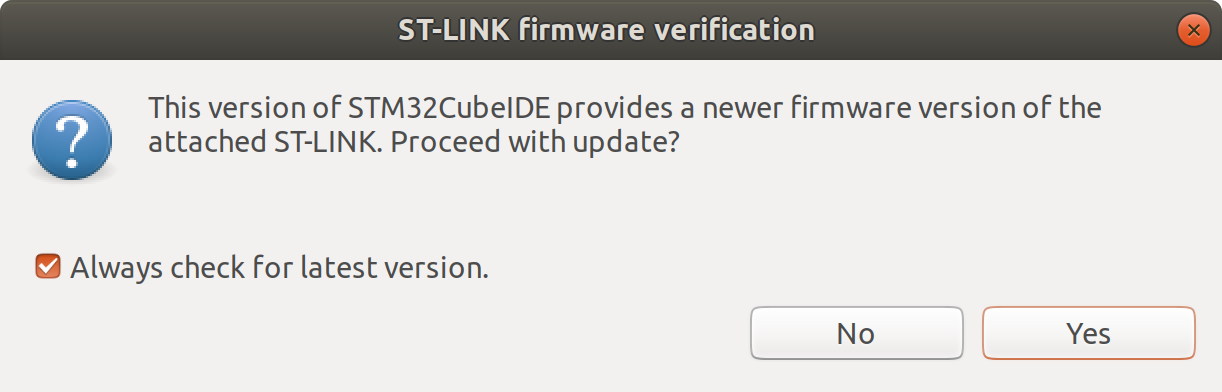 The first pop-up
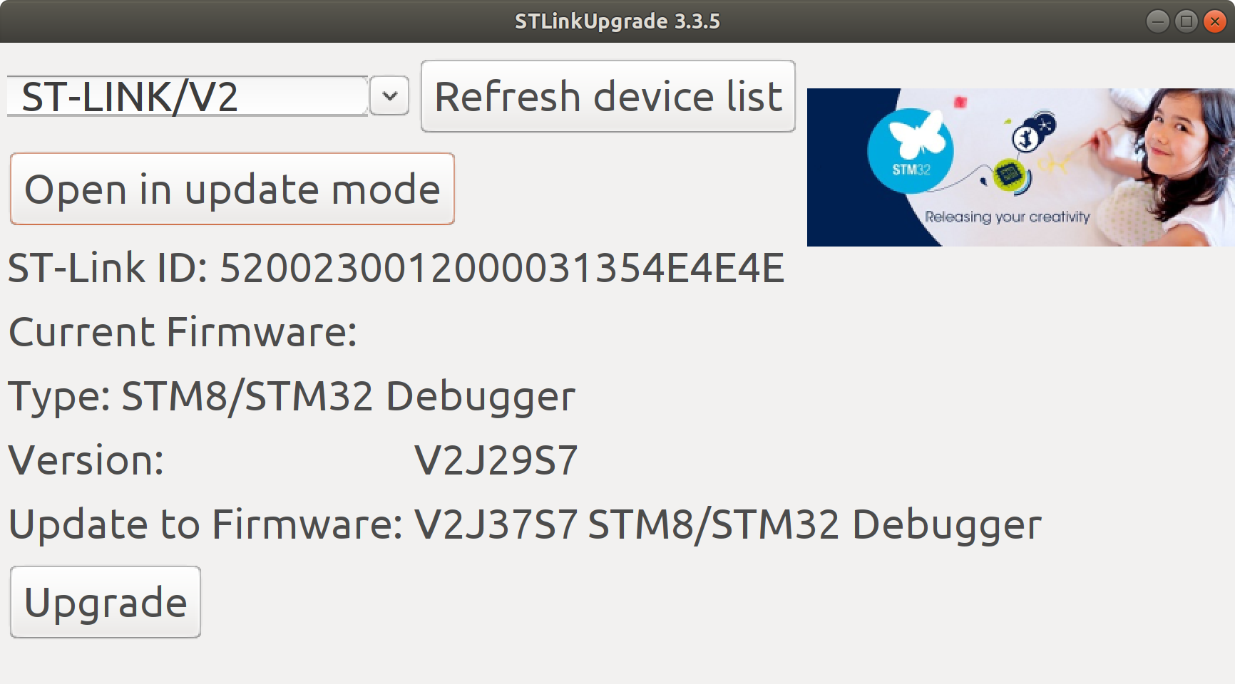 The firmware update pop-up
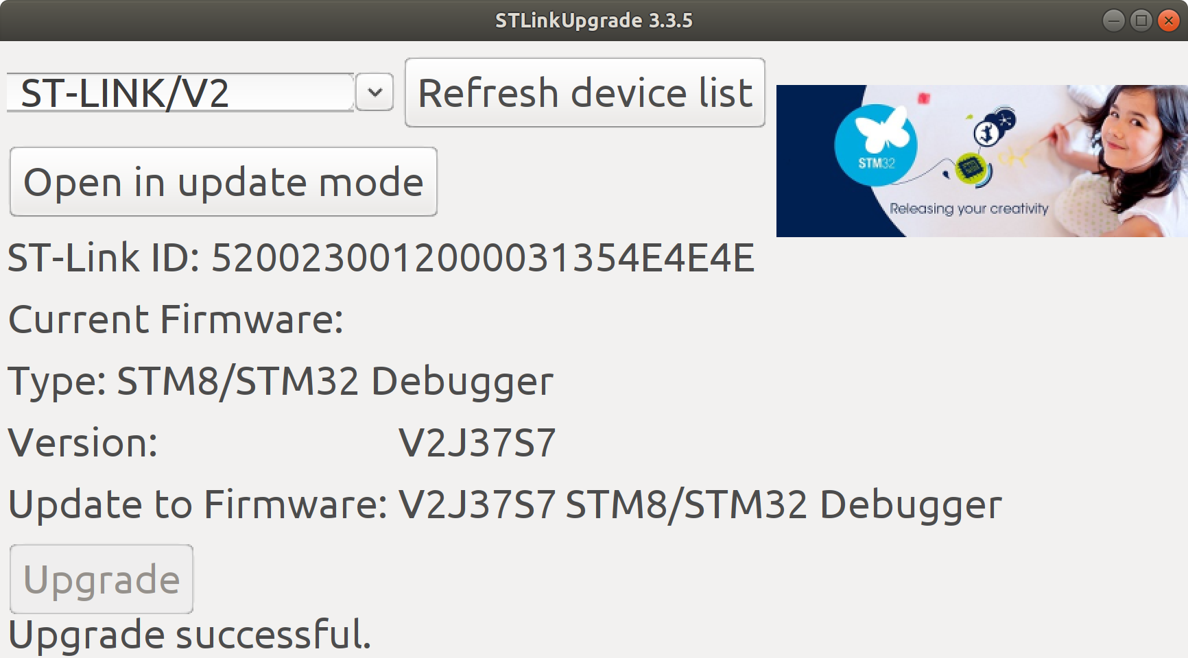 And the result after a successful update
Finally, after a lot of set-up, we get blinky! The Embedded For Everyone Wiki has a good image to represent my general state after getting it working.

Conclusion
Hopefully if you’re following along, at this point you’ll have a working blinky example. If you want to continue with STM32Cube IDE and ST’s HAL, this is the point where you start learning common HAL functions and building prototypes with it. You can also go back to the MCU configuration page and set more pins, like the external clock, and the user-controlled button. Now, I’m ambivalent about the HAL, but I frankly dislike the IDE. It feels like it’s hiding too much of the nitty gritty. And it’s repeated hanging while switching between the MCU configuration and the C code is an absolute deal-breaker. So my next steps will be attempting to get blinky with a different, hopefully simpler toolchain.
I’m also starting an embedded systems unit testing class on udemy, so I may also incorporate some testing frameworks in my next setup, since a project without tests is a side-project, not something for production.