Netgear DM 200 Modem Breakdown - The Hardware Side
Now that I’ve poked around the software side of things on my DM 200 modem, it’s now time to poke some hardware!
This is a part of my series on taking apart the netgear DM 200 modem
For more posts on this, see below
- Netgear DM 200 Modem Breakdown - The Software Side
- Netgear DM 200 Modem Breakdown - The Hardware Side (You are Here)
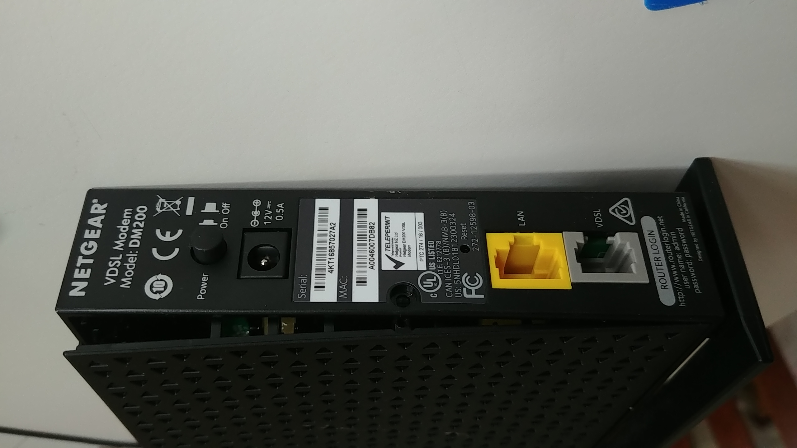
First things first, get the case open. Happily, there’s a very obvious screw on the back of the case, and a standard TR8 torx screwdriver removes it. The next bit was less obvious, but I had the openwrt website to help out. I used some picks from my ifixit repair kit to pop open the side of the case, and voila, the PCB was revealed.
 Popping open the side
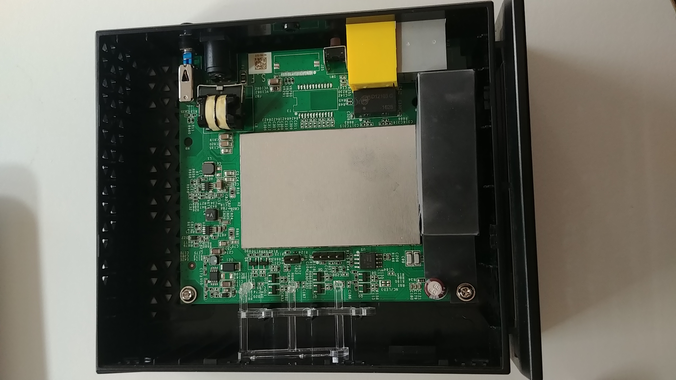 The PCB revealed!
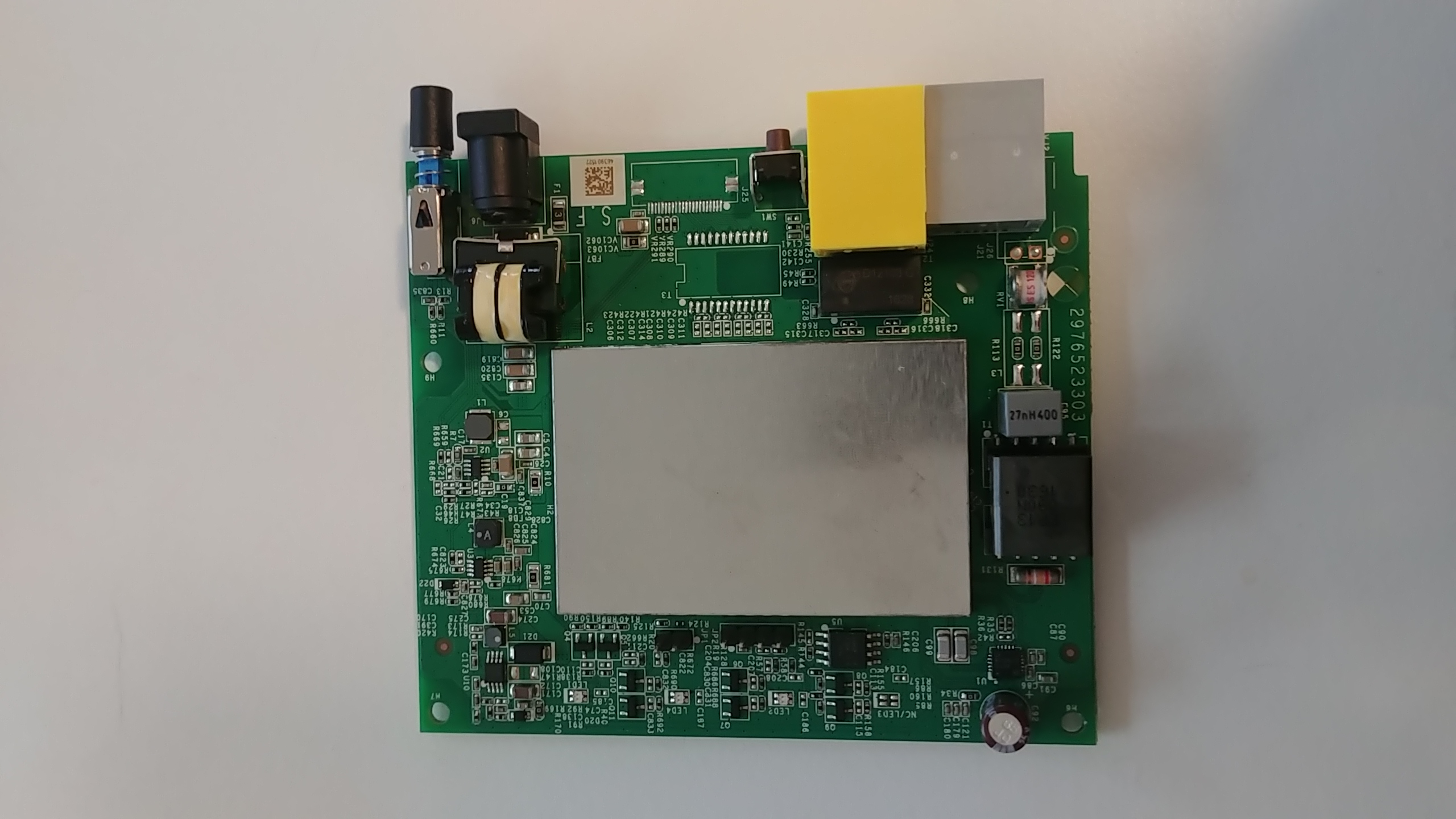 Front of the PCB
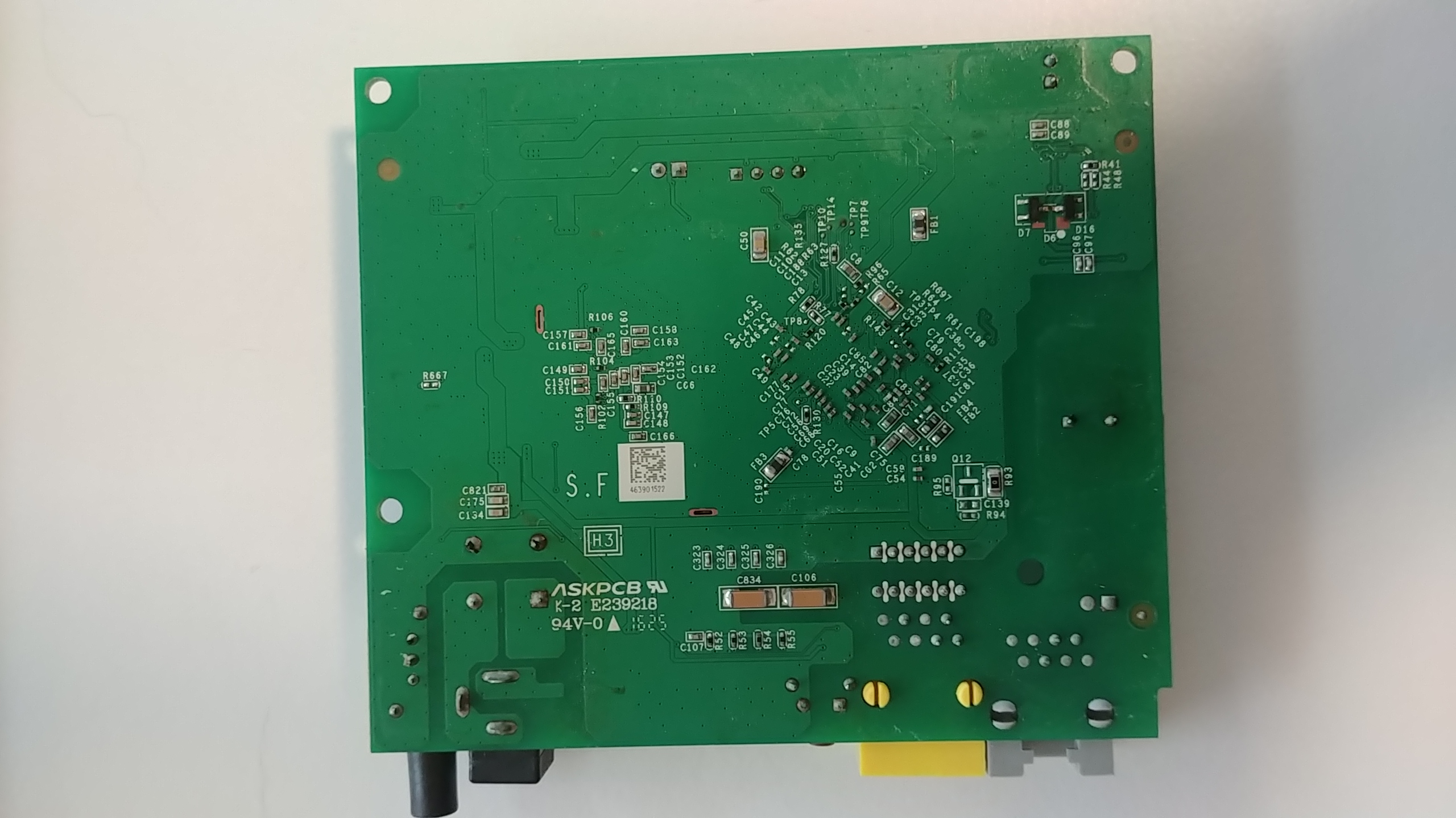 Back of the PCB
Before I could remove it from the case, I had to remove some clear molded plastic clipped over the top of it. The plastic redirects the LED lights from the board to the outside of the case, which feels very clever and very simple, a sign of good design in my books. Once that’s taken out, the board is secured by two more screws, also TR8, and then the board is freed. The first obvious thing is the huge metal box, soldered into the middle of the board. I would guess that it’s ground for the board, since all electronics need a ground. And possibly it doubles as protection for some more sensitive chips? Looking at the back of the board, I can see things are soldered in underneath the metal casing, so that seems to support my hypothesis. I’m immediately tempted to try to desolder it to see what’s underneath, but I’m trying to minimize potential damage for now, so I’ll leave that for another time. The next interesting thing is all these IC chips with mysterious letters and numbers stamped on them! I have a vague understanding you can find the chips based on these serial values, and then get the chip documentation online, which tells you what they do. So, lets start doing that!
The Hardware
Winbond
First, this rather large-ish chip that says “Winbond” in large letters.
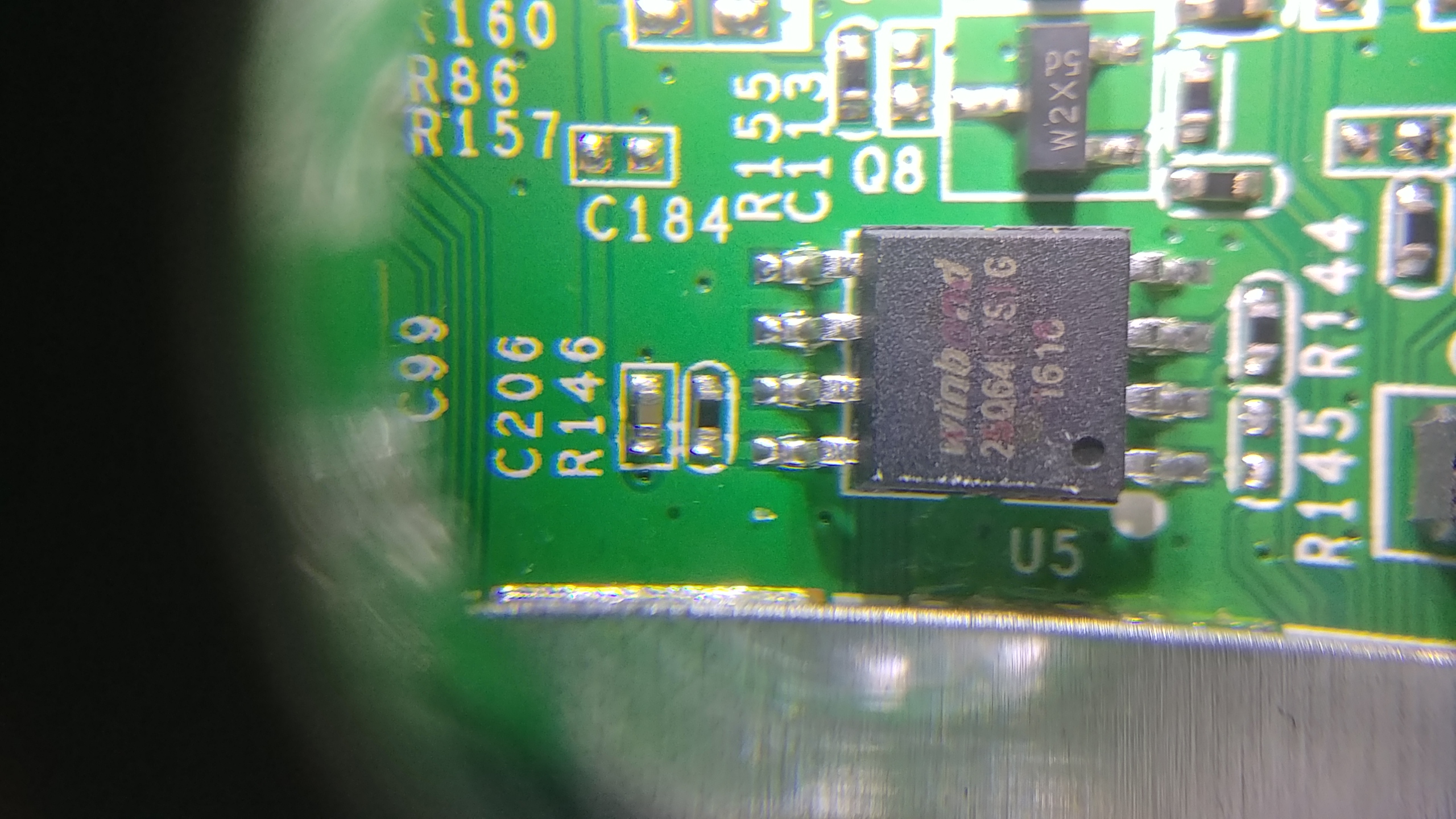
From what I can tell it’s an 8-pin chip, and the writing is “Winbond 25064 FVSIG1618”. It’s a bit roughed up as you can see, so I’m kind of guessing, but that seems a good initial thing to google. After searching around a bit, I discover it may actually be W25Q64FVSIG, so that’s a Q, not a 0 like I thought. Jotrin has the product part (https://www.jotrin.com/product/parts/W25Q64FVSIG), but won’t give me the data sheet without making me sign up with them. Rude! Happily, datasheetq.com has no such rules, and I found the data sheet there as well: https://www.datasheetq.com/datasheet-download/840460/1/Winbond/25Q64FVAIF
The datasheet shows that it’s a particular type of W25Q64FVSSIG chip. Which is different from what the marking on the chip said. Searching through the datasheet, I found that a top marking of 25Q64FVSIG, means it is in package type SS in a SOIC-8 208mil form factor.
NOTE: SOIC stands for “Small Outline Integrated Circuit”. It’s a standardized way of packaging the circuits. SOIC-8 means it has 8 pins
Now that I know all the fancy numbers, what the heck is it? It’s a flash memory, used to store, well, something, that they want to keep even when the power is off (flash is non-volatile, so it remembers things even with the power off). The datasheet says the chip operates on a single 2.7V to 3.6V power supply. It also says it supports SPI communications. I have a ch341a that I got from the Wild West Hackin’ Fest last year, and it supposedly can read 25 SPI flash with 8 pins. So I believe I could copy everything off the chip and see what’s on it? I see another project for me soon…
NOTE: SPI stands for “Serial Peripheral Interface”, it’s a synchronous and serial communication protocol setup that is very common for embedded systems things
But before I get too deep with this chip, there’s still a couple others that look interesting.
D12103 G 1628 black box
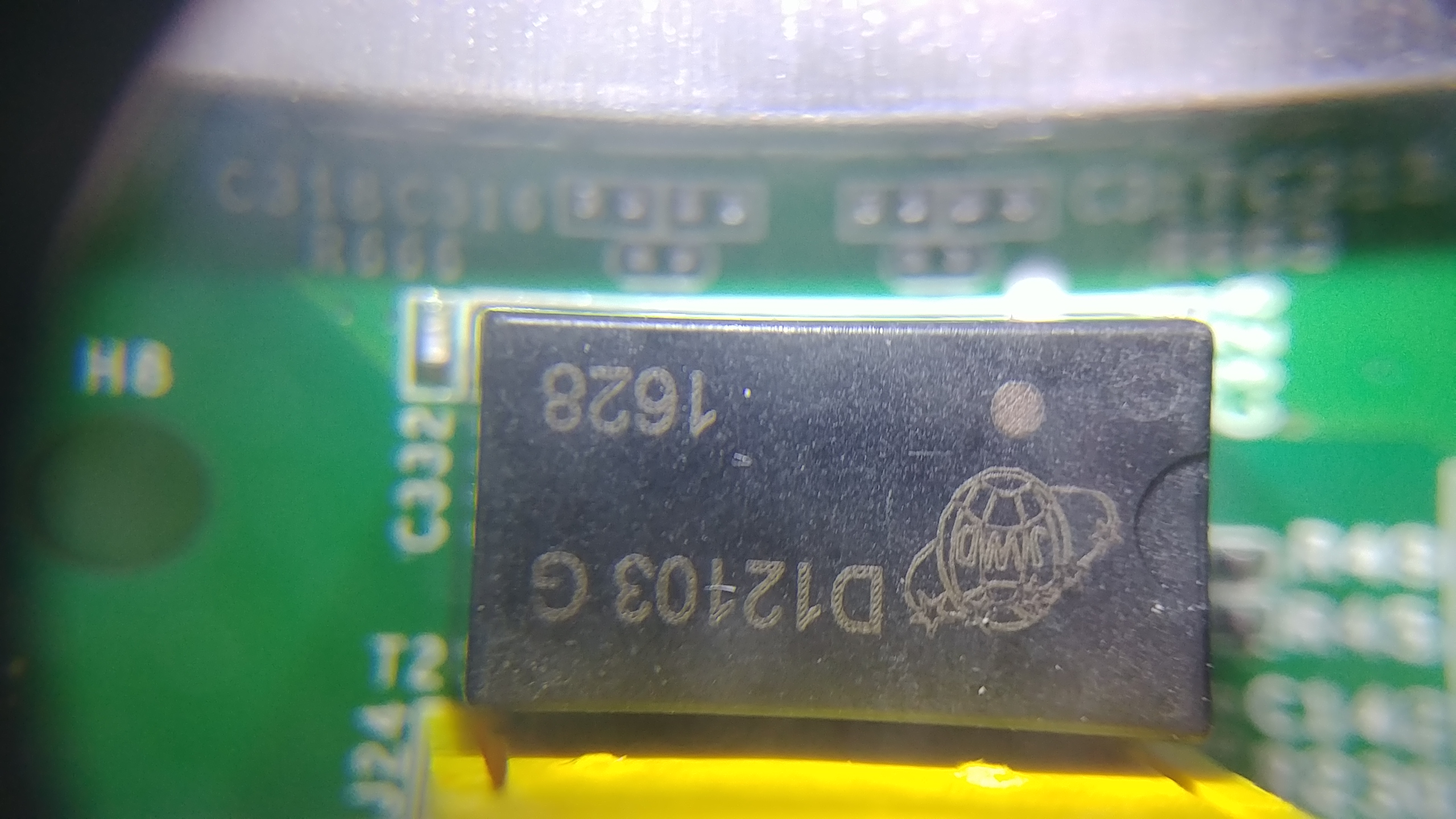 This chip is rude and doesn’t have a name!
Instead of a useful name branded on it, I get a JWD on a globe with stars. I had earlier stumbled across some IC identification websites, the main one being https://www.elnec.com/en/support/ic-logos/?method=logo, but no dice. After googling around a while, I finally found it at https://lcsc.com/brand-detail/12354.html. It says it’s the logo for Sichuan Jingweida Technology Group Co., Ltd. It also gives the list of its products:
the company mainly produces network transformer, DC converter, filter network network interface (RJ45), power transformer, power inductor, SMD, widely used in on communication, household appliances, electrical industry, pen and other high-tech fields
However, searching for D12103 G 1628 on the chip didn’t yield any datasheets or more info than that. I did find the company website and browse around there, but it seemed a dead end http://www.myjwd.com/. Since this chip is right by the ethernet plug, I’m guessing it’s a network transformer or filter network interface mentioned on the lcsc website.
Connecting
Enough googling, I want to try to fry some electronics! Well, actually that’s the exact opposite of my goal. But I do want to connect directly to the PCB using the handy dandy pin out that they left on the board. I used two other blog posts, https://jcjc-dev.com/2016/04/08/reversing-huawei-router-1-find-uart and http://www.devttys0.com/2012/11/reverse-engineering-serial-ports/ as my guides. The pin out has 4 pins, so I’m guessing it’s a UART port that was used for developers when working on the board.
UART stands for “universal asynchronous receiver-transmitter”. It has a ground, receiver (shortened to Rx), transmitter (shortened to Tx), and a power pin.
The two blog posts I linked to above give ways for determining which pin is which. One of the tricks they give is shining a flashlight through the board. This way, you can actually see the connections each pin has, and use that as an initial guess.
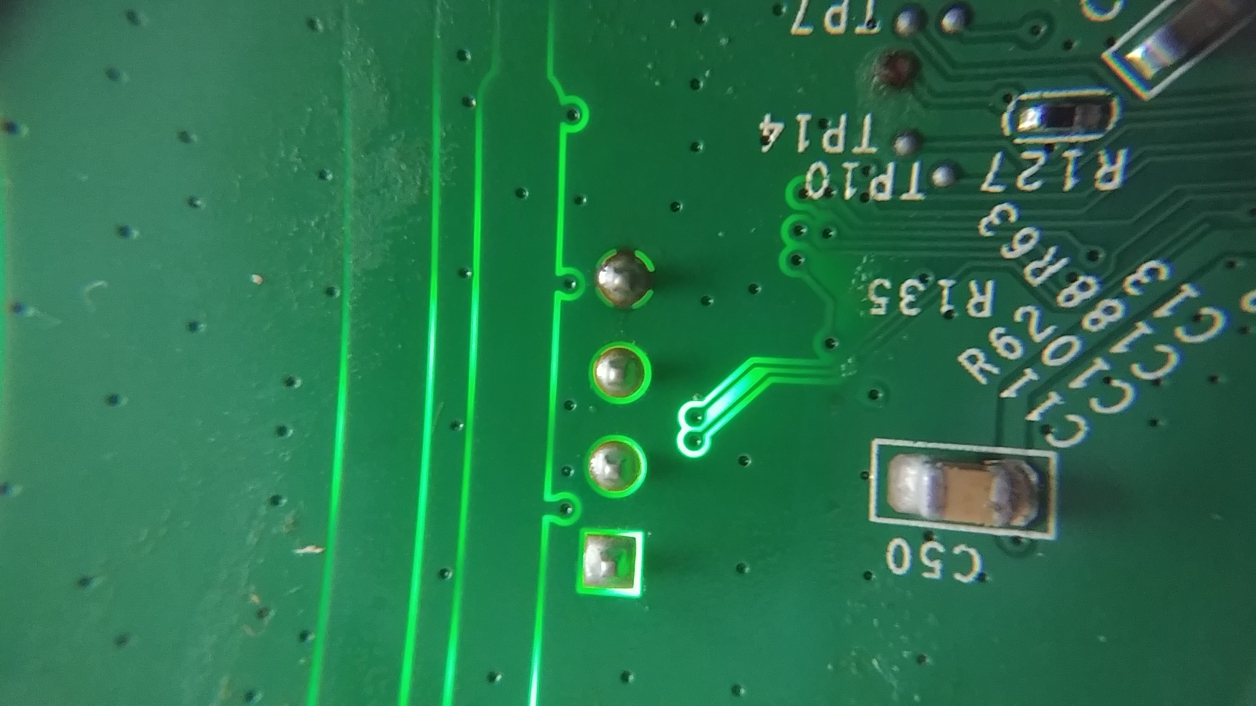
It certainly doesn’t look like the pins in the other blog! There’s a square connection, two circles, and one that looks to have a dark line at the top, bottom, and sides. If it is a UART connection, then the two circles that look similar are probably the Rx and Tx pins, with the wonky looking ones are the ground and power. But how to find out which ones are which?
It’s time for some multimeter use!
Finding Ground and Power
First, figure out which pin is ground. My theory is that the large metal cover on part of the PCB is doubling as ground for this device. Why have a huge chunk of metal in a device if you’re not using it as ground? So that means I can use my multimeter’s continuity test to see which of the pins connects to the metal cover, and that’ll be my ground!
NOTE: a continuity test on a multimeter sets it so the multimeter will make a loud beep noise when the two probes are electronically connected to each other. You can touch the probes together directly to hear the noise, or, more usefully, two points on a piece of electronics. If it beeps, there’s a way for electricity to flow from one probe location to another. Useful for making sure electricity can even flow at all in your projects!
Touching each of the pins, from left to right in the picture, gave me the following results:
- First pin - short blip, and then silent after
- Second pin - nothin’
- Third pin - nothin’
- Fourth pin - constant noise
I’ve found ground! The fourth pin, with connections in all four directions, is the ground. The short blip from the first pin was weird, but the blog posts mention that this can happen when you try to do a continuity test on the power pin. So tentatively, it’s power.
Finding Rx and Tx
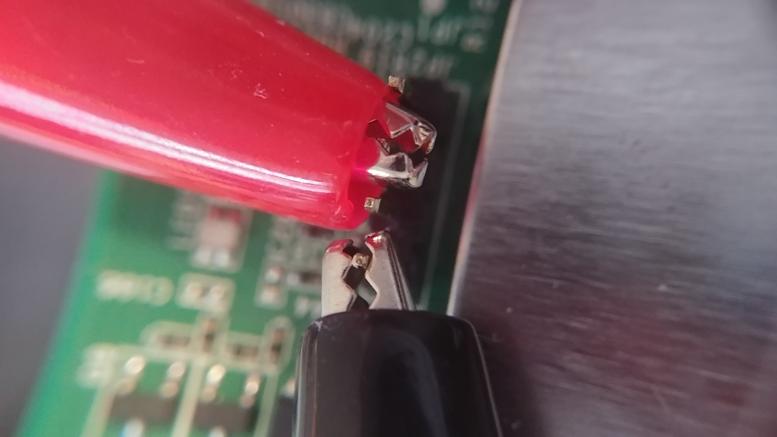
That’s about as far as I can go without powering on the modem. It’s time to turn it on! Hopefully the magic smoke stays on the inside. I can still use my multimeter for this. Multimeters excel at measuring voltage (that’s kind of their main function), and the whole point of UART is bouncing voltage up and down on the transmitting pin in order to send data. So the plan: Connect my multimeter up to the non-ground pins one by one, and watch the voltage amount on my multimeter. If there’s one that fluctuates a lot, that’s probably the transmit pin. According to the blog post http://www.devttys0.com/2012/11/reverse-engineering-serial-ports/, most data is sent when it first boots up. So I’ll be turning the modem off between each test. I also want to be monitoring the multimeter’s screen, not staring at the probes I’m holding on very tiny pins. So I grabbed some double sided alligator clip wires, to clip to the pins and the probes. And the board needed to be held steady, so I grabbed my third hand, and connected everything up. After all this setup, I was ready to go!
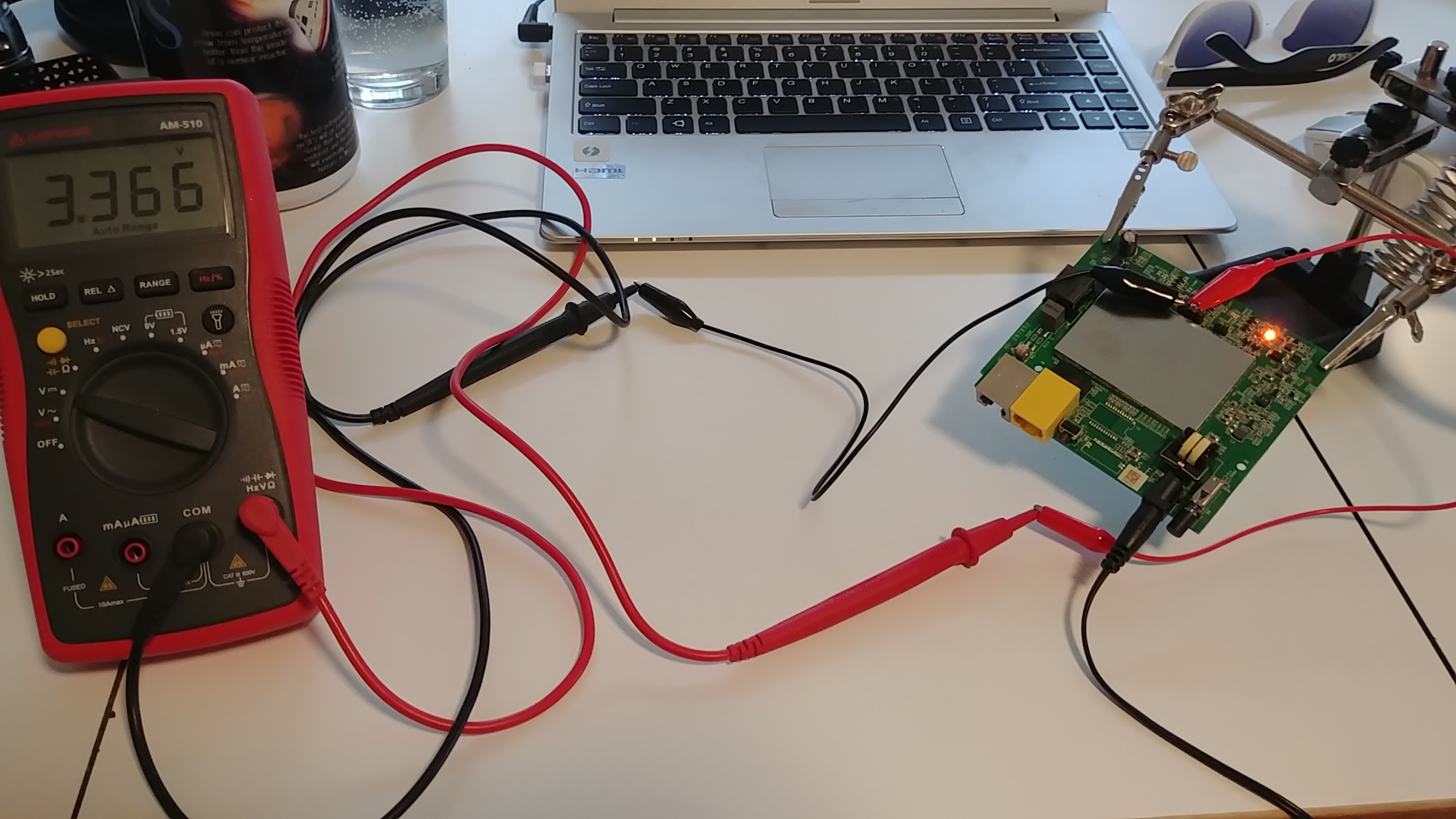
Going pin by pin, I got the following results:
- Pin 1: steady 3.3 volt
- Pin 2: variable between 3.3 and 2.4
- Pin 3: steady 3.3 volts
By guessing the Tx and Rx pins will have the same trace patterns, I came up with a final result:
- Pin 1: Power
- Pin 2: Tx
- Pin 3: Rx
- Pin 4: Ground
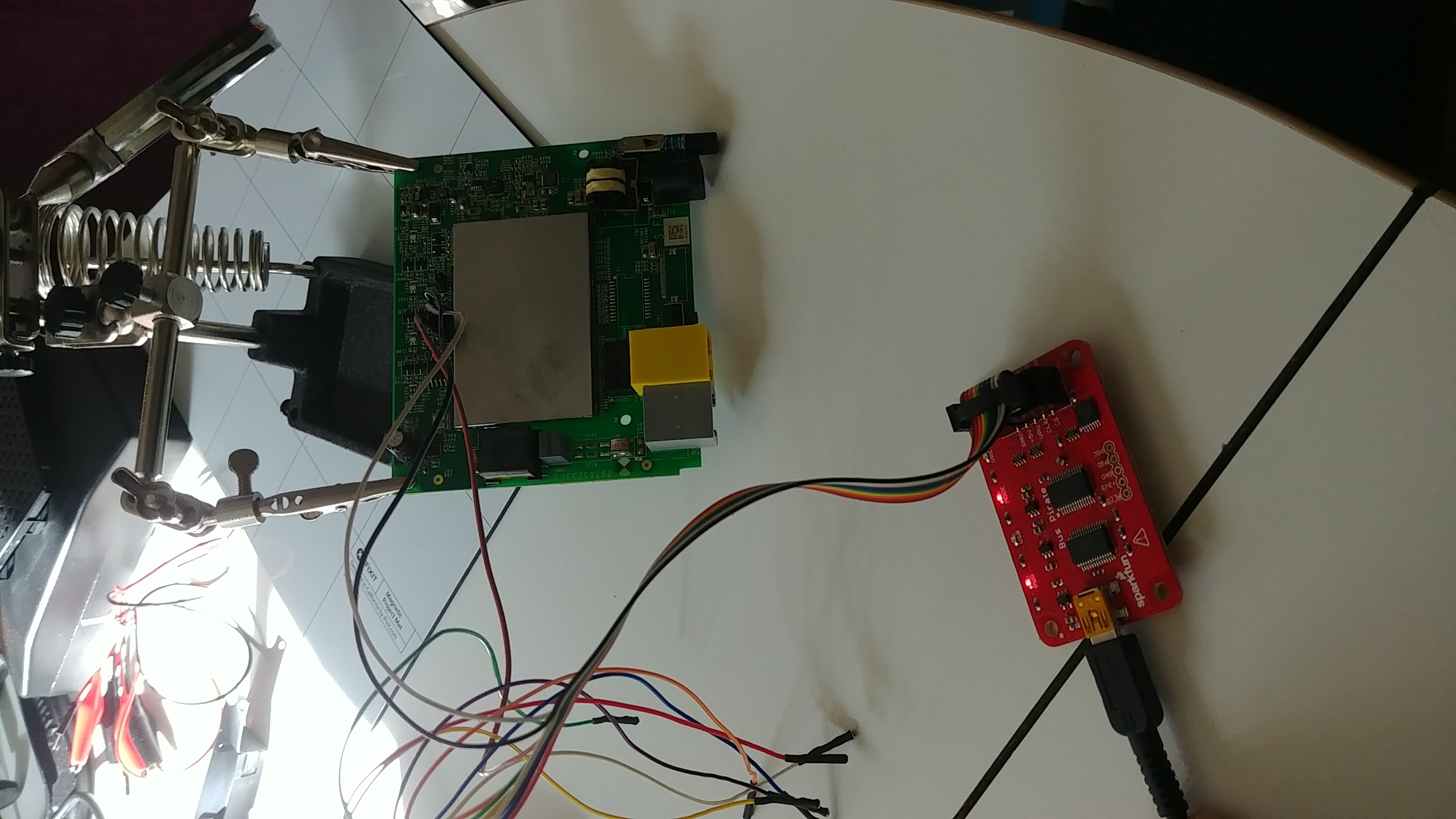
Now that I’ve done all this, I need to actually connect to the pins. Luckily, I have a bus pirate just sitting around, which supports UART communications!
Using the bus pirate
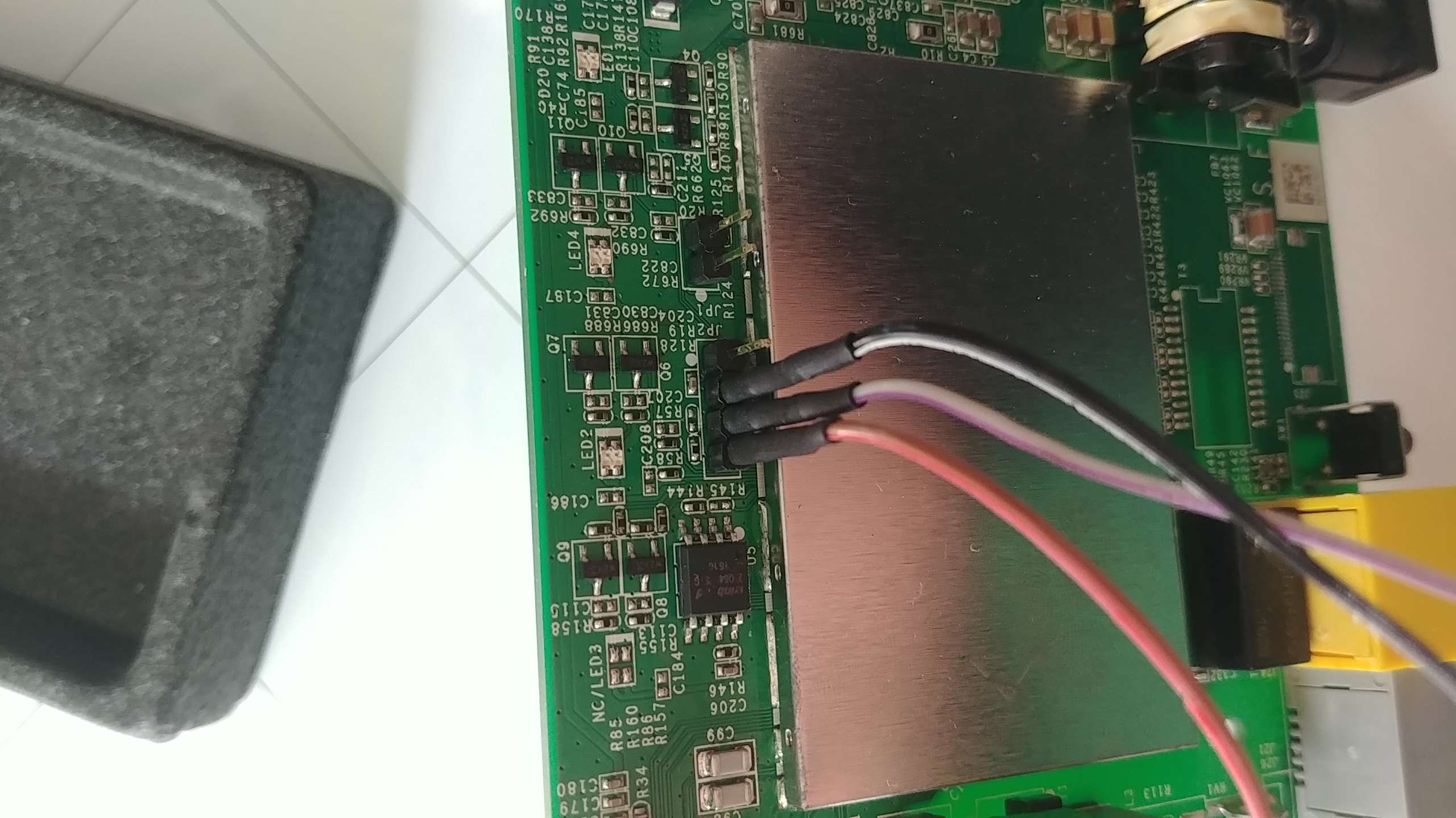
I may do a separate post later about how I did initial set up for the bus pirate. I used the graphic at https://learn.sparkfun.com/tutorials/bus-pirate-v36a-hookup-guide to figure out which color wire should connect to which pin on the modem.
Connect:
- Rx of bus pirate (black wire) to Tx of router (pin 2)
- Tx of bus pirate (grey-ish wire) to Rx of router (pin 3)
- Ground of bus pirate (brown, kinda, wire) to ground pin (pin 4)
I don’t need to connect the power pin because I won’t be powering the modem, I’ll let it stay plugged in like normal.
One last aspect of UART is that it has a specific baudrate that different UART connections use to communicate. How do you know which rate to use? Well, you don’t. There’s a bunch of standard ones, though, so I guessed during the setup of my bus pirate, and managed to get it right the first try!
With the bus pirate plugged into my computer, I used the screen command to connect to it.
NOTE: when using
screen, you can enterCtrl+athenHto log output of screen into a screenlog.0 file. I did this so I can review all the output of the modem later
The bus pirate talks to my computer at a baudrate of 115200, and the USB connection was at /dev/ttyUSB0, so to connect to the bus pirate from my computer I typed:
screen /dev/ttyUSB0 115200
In bus pirate, I changed the mode to UART and set connection requirements. Once that was done, I turned on the modem and waited for something to happen. Below is a capture of the screen while setting up, then what happens once it’s turned on (bus pirate set up ends with the line that just says “Ready”)
HiZ>m
1. HiZ
2. 1-WIRE
3. UART
4. I2C
5. SPI
6. 2WIRE
7. 3WIRE
8. LCD
9. DIO
x. exit(without change)

(1)>3
Set serial port speed: (bps)
1. 300
2. 1200
3. 2400
4. 4800
5. 9600
6. 19200
7. 38400
8. 57600
9. 115200
10. BRG raw value

(1)>9
Data bits and parity:
1. 8, NONE *default
2. 8, EVEN
3. 8, ODD
4. 9, NONE
(1)>1
Stop bits:
1. 1 *default
2. 2
(1)>1
Receive polarity:
1. Idle 1 *default
2. Idle 0
(1)>1
Select output type:
1. Open drain (H=Hi-Z, L=GND)
2. Normal (H=3.3V, L=GND)

(1)>2
Ready

ROM VER: 1.1.4
CFG 05

ROM VER: 1.1.4
CFG 05

DDR autotuning Rev 1.0
DDR size from 0xa0000000 - 0xa3ffffff
DDR check ok... start booting...


U-Boot 2010.06-12284-ga4702df (Mar 03 2016 - 13:07:38)

DM200 (hw29765233p8p0p64p0p0) UBoot-v2010.06 dni1 V0.9
CLOCK CPU 500M RAM 250M
DRAM:  64 MiB
In:    serial
Out:   serial
Err:   serial
8192 KiB W25Q64 at 0:3 is now current device
Net:   Internal phy(FE) firmware version: 0xc434
vr9 Switch
.
.
.
This goes on for a while, I'm stopping it here
It works! Cue dancing around and pumping my fists victoriously. Now, I have no idea what to do with all this info spewing on my screen, but this is the first time I’ve done any sort of reverse engineering of hardware, so I think I deserve to celebrate.
After I let it continue to spew mysterious log info for a while, it finally settles down, and gives me root busybox access! However, it’s not all fun and games. The modem is not happy about not being able to complete the PPPoE discovery, and periodically just throws it into my shell as I try to type. I tried a few commands, but got a bit annoyed at the extra info popping up.
NOTE: PPPoE stands for “Point-to-Point Protocol over Ethernet”. It’s used by most DSL providers for authentication and encryption purposes. It’s for sending packets to the ISP’s network before going to the rest of the internet, from what I can tell on wikipedia.
This is a DSL modem, and it’s not connected to any internet, so I’m guessing that’s why it fails. I could potentially work around that, but honestly, I’m not sure what all I can do from here, so I’m leaving it alone. Here’s the output of the shell and my attempts at playing around.
Timeout waiting for PADO packets
Unable to complete PPPoE Discovery
Timeout waiting for PADO packets
Unable to complete PPPoE Discovery
Timeout waiting for PADO packets
Unable to complete PPPoE Discovery


starting pid 345, tty '/dev/ttyLTQ0': '/bin/ash --login'


BusyBox v1.17.1 (2016-04-29 07:02:59 EDT) built-in shell (ash)
Enter 'help' for a list of built-in commands.

+---------------------------------------------+
| Lantiq UGW Software UGW-6.1.1 on XRX200 CPE |
+---------------------------------------------+

root@DM200:/# [  446.710000] DSL[00]: ERROR - Function is only available in the SHOWTIME!
[  446.740000] DSL[00]: ERROR - Function is only available in the SHOWTIME!
ftpput: can't connect to remote host (60.248.155.55): Network is unreachable
Timeout waiting for PADO packets
Unable to complete PPPoE Discovery

root@DM200:/# whoami
/bin/ash: whoami: not found
root@DM200:/# ls
bin                       hardware_version          ramdisk_copy
default_language_version  hw_id                     rom
dev                       lib                       root
etc                       mnt                       sbin
firmware                  module_name               sys
firmware_region           opt                       tmp
firmware_time             overlay                   usr
firmware_version          proc                      var
flash                     ramdisk                   www
root@DM200:/# Timeout waiting for PADO packets
Unable to complete PPPoE Discovery
c[J
root@DM200:/# cat hardware
root@DM200:/# cat hardware_version
DM200
root@DM200:/# cat hw_id
29765233+8+0+64+0+0
root@DM200:/# cat firmware_v
root@DM200:/# cat firmware_version [J
V1.0.0.34
root@DM200:/# ls /bin
adduser           dmesg             mkdir             rmdir
ash               dnsdomainname     mknod             sed
busybox           echo              mount             sh
busybox2          egrep             mv                sleep
cat               fgrep             netstat           su
chgrp             getopt            nice              sync
chmod             grep              nvram             tar
chown             gunzip            pidof             touch
config            gzip              ping              true
cp                hostname          ping6             umount
datalib           ipcalc.sh         ps                uname
date              kill              pwd               usleep
dd                ln                readycloud_nvram  vi
deluser           login.sh          rev               zcat
df                ls                rm
root@DM200:/# Timeout waiting for PADO packets
Unable to complete PPPoE Discovery
Conclusion
There you have it, my first hardware reverse engineering adventure! I certainly learned a lot about datasheets, integrated circuit logos, some cool ways to use multimeters, basics of how a router/modem is set up, UART, AND basics of using bus pirate. Whew!
This was super fun, and slightly nerve-wracking, which I think means it’s something I should do more of. My other pieces of hardware are no longer safe from my prying eyes and screwdrivers!